I have seen it happen too many times on commercial job sites. A crew spends days installing a complex fluid delivery network. They finally pressurize the line, only to watch the couplings weep fluid. This frustrating and expensive scenario plagues mechanical contractors everywhere. Even a microscopic dimensional mismatch can completely ruin the mechanical seal on a grooved system. In this comprehensive guide, you will learn exactly how to measure, evaluate, and select the correct dimensions to ensure a flawless, code-compliant installation from day one.
Key Takeaways for System Sizing
Outside Diameter is the Ultimate Metric: When sizing a grooved piping system, the Outside Diameter is the single most critical measurement required to guarantee a proper mechanical seal.
Master the Terminology: Differentiating between Nominal Pipe Size and Diameter Nominal is essential for accurate global procurement and avoiding costly on-site delays.
Application Specifics Matter: Sizing tolerances and wall thickness requirements vary strictly based on the end-use application, especially when configuring life-safety networks.
Strict Fitting Compatibility: The pipe dimensions must align perfectly with the engineered specifications of the mechanical couplings to maintain system integrity and handle pressure surges safely.
Understanding the Sizing Metrics for Grooved Galvanized Steel Pipe
Accurate procurement begins with a fundamental understanding of how industrial pipes are measured and categorized. Engineers and buyers must navigate different regional standards while maintaining strict dimensional tolerances.
Looking at recent industry trends, there is a massive shift toward Building Information Modeling and modular, off-site construction in the commercial plumbing and HVAC sectors. The rising cost of skilled labor pushes mechanical contractors to rely heavily on precise pre-fabrication sizing rather than making manual, on-site adjustments. Global supply chains are also tightening quality controls. Consequently, mastering these dimensional metrics is no longer just a best practice; it is an absolute necessity for staying competitive and profitable in modern contracting.
Nominal Pipe Size vs. Diameter Nominal
Piping systems are generally specified using two primary sizing standards. Nominal Pipe Size is the standard used primarily in North America, measured in inches. In contrast, Diameter Nominal is the metric standard utilized internationally, measured in millimeters.
It is crucial to understand that the word nominal simply means in name only. A size 4 pipe does not have an exact 4-inch inside or outside diameter. Instead, it acts as a standardized designation. When procuring materials globally across different supply chains, converting these nominal designations accurately is the very first step in avoiding mismatched components on the job site.
The Critical Role of the Outside Diameter
When working with grooved systems, the Outside Diameter is the metric that dictates success or failure. Mechanical joints function by utilizing a heavy-duty coupling housing that clamps around the exterior of the pipe. This housing compresses an elastomeric rubber gasket directly against the outer steel surface of the pipe.
If the dimension is even slightly out of tolerance, the housing will either fail to close completely if it is too large, or fail to compress the gasket sufficiently if it is too small. Both scenarios lead to inevitable leaks. A standardized Outside Diameter ensures that pipes from various global manufacturers can be seamlessly connected using standard mechanical fittings.
Wall Thickness and Pipe Schedules
While the exterior dimension remains constant for a given nominal size, the internal diameter fluctuates based on the wall thickness of the pipe, which is defined by its Schedule. Common classifications include Schedule 10, Schedule 40, and Schedule 80.
For instance, a Schedule 40 pipe features a thicker, heavier wall than a Schedule 10 pipe. Because the exterior must remain firmly fixed to fit inside the mechanical couplings, the extra steel in a Schedule 40 pipe reduces the internal flow area. Wall thickness directly impacts the maximum allowable working pressure of the network and dictates the specific type of grooving method that can be safely applied.
How to Accurately Measure and Size Your Pipe
Determining the correct dimensions requires precision tools and a clear understanding of the mechanical joint geometry. Guesswork or relying on outdated specification sheets during this phase often leads to project delays and failed hydrostatic pressure tests.
Measuring the Actual Outside Diameter
Imagine standing in a dimly lit mechanical room trying to verify pipe deliveries. A standard retractable tape measure will simply not cut it here. Procurement and quality control teams must utilize precision Vernier calipers or specialized Pi tapes, also known as diameter tapes.
A Pi tape is wrapped tightly around the circumference of the pipe and directly outputs the exact Outside Diameter. Before taking this measurement, ensure the pipe surface is wiped clean of any factory cutting fluids or debris. This measurement must be taken near the raw end of the pipe where the mechanical coupling will eventually be seated, ensuring it falls perfectly within the specified tolerance range of the manufacturer.
Determining the Required Groove Dimensions
The groove itself must be formed to exact specifications so the coupling housing engages correctly. There are two primary methods for creating these channels. Roll grooving uses a specialized machine to displace the metal radially inward. This method is the industry standard for thinner-walled pipes because it does not remove any raw material, thereby preserving the structural integrity of the pipe. Cut grooving utilizes a lathe-like machine to physically mill away metal. This requires a much thicker wall to ensure the remaining steel thickness safely meets high-pressure safety standards.
Regardless of the fabrication method, three vital measurements must be verified. First is the A Dimension, which is the smooth distance from the end of the pipe to the edge of the groove, acting as the gasket seating area. Second is the physical Groove Width. Third is the Groove Depth.
Grooving Method
Ideal Pipe Schedule
Material Removal
Primary Application
Pressure Rating Impact
Roll Grooving
Schedule 10 to Schedule 40
None (Cold Formed)
Commercial HVAC, Fire Sprinklers
Maintains full pipe wall integrity
Cut Grooving
Schedule 40, Schedule 80
Yes (Machined)
High-Pressure Industrial, Mining
Reduces wall thickness at groove base
Sizing Standards for Fire Protection Systems
When engineering life safety systems, the sizing of a grooved fire protection pipe demands strict adherence to international manufacturing and installation standards. Unlike general water distribution networks, fire suppression systems remain static for long periods but must perform flawlessly under extreme hydrostatic pressure during an emergency. Accurate sizing is not merely a matter of operational efficiency; it is a critical compliance requirement.
Strict Code Compliance
Fire protection systems are governed by rigorous codes, most notably the National Fire Protection Association standards, such as NFPA 13. For a galvanized steel pipe to be legally utilized in these applications, it must often carry certifications from Underwriters Laboratories and Factory Mutual. These testing bodies mandate exact dimensional tolerances for the Outside Diameter and overall wall thickness of the pipe.
If a pipe is undersized or oversized by even a fraction of a millimeter, the mechanical coupling may fail to grip the groove properly. During a fire event, the sudden surge of water pressure from the heavy-duty fire pumps could cause an improperly sized joint to blow out, leading to catastrophic system failure.
Common Sizes in Sprinkler Systems
In commercial and industrial fire sprinkler layouts, specific pipe sizes are standardized to calculate water flow and friction loss accurately. Below is a reference detailing the most frequently used sizes for fire sprinkler mains and branch lines, along with their exact exterior requirements.
Diameter Nominal
Nominal Pipe Size
Exact Outside Diameter
Typical Application
DN50
2 inch
60.3 mm
Branch lines and small arrays
DN80
3 inch
88.9 mm
Cross mains and risers
DN100
4 inch
114.3 mm
Primary cross mains
DN150
6 inch
168.3 mm
Main risers and pump headers
Galvanized Coating Thickness
The hot-dip galvanizing process adds a protective layer of zinc to both the interior and exterior of the steel pipe to prevent corrosion. According to standards like ASTM A53, this zinc coating typically ranges from 50 to 80 microns in thickness. While this may seem negligible to the naked eye, this added thickness must be accounted for during the sizing and grooving process.
Furthermore, if the galvanizing is applied unevenly, or if zinc pooling occurs near the pipe ends, the dimension may temporarily exceed the maximum allowable tolerance. High-quality manufacturing and strict quality control are necessary to ensure the pipe ends remain perfectly smooth. An irregular galvanized surface can prevent the elastomeric gasket from seating correctly, leading to micro-leaks over time.
Matching Your Pipe with the Right Mechanical Fittings
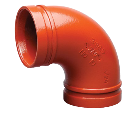
Determining the correct pipe size is only half the equation. The pipe must be perfectly matched to the corresponding fittings. A mechanical joint steel pipe network relies on the symbiotic relationship between the pipe groove, the elastomeric gasket, and the coupling housing. If the sizing is mismatched, the structural integrity of the entire piping network is compromised.
The Mechanics of the Joint
To fully grasp why sizing is so critical, one must understand how a mechanical joint operates under pressure. The system consists of three primary components: a resilient rubber gasket, a ductile iron or steel coupling housing, and heavy-duty track head bolts with nuts. Standard high-quality fittings are often cast from ductile iron conforming to ASTM A536 Grade 65-45-12, providing immense tensile strength.
When the coupling is assembled over the grooved pipe ends, the gasket wraps around the steel, bridging the tiny gap between the two sections. As the bolts are tightened, the housing compresses the gasket securely against the pipe. Simultaneously, the internal keys of the coupling housing drop seamlessly into the grooves. The system is designed so that internal fluid pressure actually forces the lips of the gasket tighter against the pipe surface, continuously enhancing the seal.
Case Study: Sizing for DN114 Systems
To illustrate the precision required, consider a standard DN114 commercial chilled water system. The nominal size indicates a 4-inch pipe, but the actual sizing metric that matters is the exact Outside Diameter, which is 114.3 mm.
For this specific size, standard roll groove specifications dictate that the groove diameter must be precisely 110.08 mm, with a tight tolerance of only plus 0.00 to minus 0.38 mm. The A dimension must be exactly 15.88 mm. If a contractor hastily rolls the groove to 111.00 mm, the groove is too shallow. The coupling keys will not fully engage, risking a catastrophic blowout. Utilizing precision-measured National Standard Victaulic-style fittings eliminates guesswork on the job site and ensures the joint will achieve its maximum rated working pressure.
The Advantages of Accurate Sizing for Rapid Deployment
In modern commercial construction, time is one of the most expensive commodities. The primary reason engineers and contractors specify these networks over traditional welded or threaded systems is the sheer speed of assembly. However, this system only functions as a quick installation piping solution if the initial sizing and grooving are executed with absolute accuracy.
Speeding Up Project Timelines
Traditional pipe joining methods, such as welding, require highly skilled labor, hazardous hot work permits, fire watches, and extensive X-ray testing of the welds. Threading large-diameter pipes is equally time-consuming and requires lugging heavy machinery onto the job site.
Accurately sized grooved piping eliminates these hurdles entirely. Because the pipe ends are prepared precisely at the fabrication shop, the actual connection process in the air takes only a few minutes. Installers simply lubricate the gasket, slip it over the pipe ends, place the housing over the gasket, and tighten two bolts with a standard impact wrench.
Reducing Labor Costs and Downtime
Labor costs often account for the largest percentage of a mechanical contractor budget. By utilizing accurately sized grooved systems, contractors can reduce installation time by up to three to four times compared to welding. In addition, because the installation does not require hot work, it eliminates the need to shut down operational facilities for safety reasons. This is particularly advantageous in retrofit projects within active hospitals or data centers, where minimizing downtime is critical.
Sourcing High-Quality Materials
Achieving the perfect fit requires starting with superior raw materials. The sizing accuracy of a grooved joint is heavily dependent on the manufacturing quality of the pipe itself. Procurement professionals must be highly diligent when selecting manufacturing partners.
What to Look for in a Supplier
When sourcing industrial piping, consistency is the most vital attribute. Buyers should look for suppliers who implement stringent quality control measures and possess international certifications such as ISO 9001.
Key indicators of quality include consistent wall thickness and perfect pipe roundness. If a pipe is slightly oval, the grooving machine will inherently create an uneven groove depth, leading to a high probability of leakage. Reputable suppliers will provide detailed Mill Test Reports that verify the chemical composition and yield strength of the steel, ensuring the pipe can withstand the mechanical stress of the grooving process without cracking.
Custom vs. Standard Lengths
Pipes are typically supplied in standard lengths, such as 21 feet. However, complex mechanical rooms require highly varied pipe lengths. When calculating the total length of pipe needed for a specific run, engineers must account for the mechanical coupling gap.
Unlike threaded pipes that overlap, grooved pipes are designed to have a slight gap between the pipe ends within the coupling housing. This gap allows for crucial thermal expansion and angular deflection. When fabricating custom lengths, this gap must be subtracted from the overall center-to-center measurement to ensure the final assembly fits perfectly into the designated space.
Common Sizing Mistakes to Avoid During Procurement
Even seasoned procurement teams can make costly errors when specifying and ordering grooved piping systems. Avoiding these common pitfalls is essential for maintaining project budgets and strict safety standards.
Confusing Inside Diameter with Outside Diameter
This is arguably the most frequent and costly mistake in pipe procurement. For fluid flow calculations, mechanical engineers focus heavily on the Inside Diameter. However, for joint assembly, the mechanical couplings grip the outside of the pipe.
If a purchasing agent orders a mechanical coupling based on the nominal inside diameter of the pipe, the fitting will be fundamentally incompatible. Always remember that in the world of grooved piping, the Outside Diameter is the absolute, non-negotiable metric.
Overlooking Minimum Wall Thickness for Cut Grooving
A common mistake on job sites is attempting to cut-groove a thin-walled pipe to save time. Removing metal from a Schedule 10 pipe leaves the wall far too thin to handle system pressure, resulting in immediate structural failure. Cut grooving should generally be reserved for Schedule 40, Schedule 80, or heavier steel pipes. If you are procuring lighter schedule pipes to save on weight and material costs, you must explicitly specify roll grooving.
Mixing Metric and Imperial Standards Incorrectly
Global supply chains often require converting between imperial and metric measurements. A dangerous mistake is assuming a direct mathematical conversion equals the correct nominal pipe size.
For example, a direct mathematical conversion of 2 inches is 50.8 mm. However, a 2-inch Nominal Pipe Size actually has a standardized Outside Diameter of 60.3 mm. If a buyer requests a 50 mm pipe assuming it matches a 2-inch American standard coupling, the parts will simply not fit together. Always rely on standardized dimensional charts rather than basic calculator conversions.
Conclusion
Determining the correct size of a grooved galvanized steel pipe ultimately comes down to mastering the Outside Diameter, understanding precise groove specifications, and matching the pipe perfectly to the engineered mechanical fittings. By utilizing precision measurement tools, adhering to strict code compliances, and avoiding common procurement pitfalls, contractors can ensure a safe, reliable, and leak-free system. Precision in the procurement and sizing stage guarantees the speed and reliability of the final installation, saving both time and money on the job site. If you are looking for high-quality, perfectly toleranced piping and standard fittings for your next commercial project, explore the comprehensive inventory at czwhsteel.com to ensure a flawless installation.
FAQ
What is the difference between roll grooving and cut grooving on a galvanized steel pipe?
Roll grooving uses heavy mechanical pressure to displace the steel, forming an indentation without removing any material. This method is ideal for thinner-walled pipes, such as Schedule 10, as it maintains the structural integrity of the pipe. Cut grooving physically machines a channel into the pipe exterior, removing metal. It provides a highly precise groove but requires a thicker pipe wall, such as Schedule 40 or 80, to ensure the remaining wall thickness can safely handle the internal pressure of the system.
Can I use mechanical joint steel pipe for high-pressure applications?
Yes, mechanical grooved joints are highly capable of handling high-pressure applications, provided the system is engineered correctly. The specific pipe schedule, the precise depth of the groove, and the pressure rating of the chosen coupling must all align with the maximum operating pressure of the system. Always consult the pressure rating charts of the manufacturer, as heavy-duty rigid couplings can often handle pressures exceeding 1,000 psi when paired with the appropriate pipe wall thickness.
How does DN114 translate to inches?
The designation DN114 is a metric term that correlates to the North American 4-inch Nominal Pipe Size. However, neither the number 114 nor 4 represents the exact measurement used for fitting mechanical couplings. The exact standardized Outside Diameter for a DN114 or 4-inch pipe is 114.3 millimeters, which equates to exactly 4.500 inches. This is the critical measurement required for proper groove and coupling engagement.
Why is grooved piping preferred for fire protection systems?
Grooved piping is the industry standard for fire protection because it offers rapid, highly reliable installation without the extreme fire hazards associated with on-site welding. Furthermore, grooved mechanical joints can be engineered as flexible couplings. This inherent flexibility allows the piping network to accommodate thermal expansion, contraction, and critical seismic movement, ensuring the fire suppression system remains completely intact and functional during earthquakes or building settling.
How do you measure the A dimension on a grooved pipe?
The A dimension is measured from the true end of the pipe to the closest edge of the groove. This smooth section of steel acts as the primary seating surface for the elastomeric gasket. To measure it accurately, inspectors use a specialized groove gauge or a precision Vernier caliper. The pipe end must be cut perfectly square; if the cut is angled, the A dimension will vary around the circumference, leading to an uneven gasket seal and potential leaks.
What schedule pipe is required for cut grooving?
Cut grooving physically removes steel from the outer wall of the pipe. Therefore, it is generally restricted to heavier-walled pipes, typically Schedule 40, Schedule 80, or greater. Using a cut groove on a Schedule 10 pipe leaves the remaining steel at the base of the groove too thin to safely contain fluid pressure, violating structural safety codes. Always verify the minimum wall thickness requirements specified by the coupling manufacturer before machining.
Our forged threaded flanges have undergone strict quality control and testing, with excellent strength and reliability, and can withstand high pressure and harsh working environments.
CONTACT US
Phone:+86-13832718182 Email: sales@czweiheng.com WhatsApp:+86-13832718182 Add:East of Construction Machinery Factory, Yanshan County, Cangzhou, Hebei China