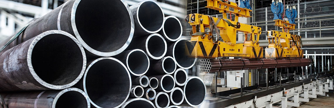
A single pipeline failure causes massive environmental damage. It paralyzes regional energy grids. It results in catastrophic financial losses. The blunt reality is that even the absolute best oil and gas steel pipe will inevitably fail if installed poorly. Sourcing premium metallurgical materials is just the foundation of any project. The long-term reliability of a hydrocarbon transport system heavily depends on field execution.
In this comprehensive guide, we explore the critical installation factors. These range from on-site handling and precision welding to trenching and hydrostatic testing. They directly dictate the performance, safety, and lifespan of pipeline infrastructure. Are you a project engineer, a procurement specialist, or a site manager? Understanding these variables is non-negotiable for guaranteeing optimal high-pressure performance.
Key Takeaways
Proper Handling Prevents Early Failure: Mechanical damage during offloading creates microscopic stress fractures. This weakens the steel pipe long before it enters the trench.
Welding Integrity Dictates Lifespan: The metallurgical quality of field welds remains the single most significant factor in preventing leaks and ensuring structural continuity.
Trenching and Bedding Prevent Stress: Incorrect backfilling and uneven trench beds introduce severe localized bending stresses. This leads to eventual pipe deformation.
Corrosion Prevention Must Continue On-Site: Flawless field joint coatings and meticulously installed cathodic protection systems are vital for defending against soil-borne corrosion.
Sourcing Matters: Pairing rigorous installation techniques with premium materials guarantees long-term asset reliability under extreme pressures.
Pre-Installation: Handling, Transport, and Storage Protocols
The lifecycle of pipeline infrastructure begins well before heavy machinery starts excavating. The pre-installation phase encompasses transport, offloading, and on-site staging. This is a highly sensitive period. Improper handling during these initial stages severely degrades the performance of the pipe. It introduces physical defects that compromise structural integrity and scrape away factory-applied corrosion barriers.
Preventing Mechanical Damage During Transport
Transporting heavy steel pipes requires strict adherence to mechanical safety protocols. The primary objective is to prevent gouges, dents, and scratches on the exterior surface. When a steel pipe incurs a deep gouge, that mark acts as a stress concentrator. Under high operational pressures, these tiny concentrators rapidly propagate into micro-cracks. This ultimately leads to a catastrophic rupture.
In practice, rigging crews must utilize appropriate lifting equipment to mitigate these risks. Bare steel cables, heavy chains, or unpadded forklift tines should never come into direct contact with the pipe body. Instead, contractors deploy heavy-duty padded slings, vacuum lifters, or nylon straps to distribute the weight evenly. Furthermore, pipes must be secured during transit using padded bolsters and tiedowns. This prevents them from shifting, rubbing against one another, or violently impacting the transport trailer.
On-Site Storage Best Practices
Once a flatbed truck arrives at the staging area, proper storage protocols kick in immediately to maintain pristine condition. Pipes left resting directly on native soil are highly susceptible to moisture absorption. They attract soil-borne contaminants and experience accelerated localized rusting.
To prevent environmental degradation, crews stack pipes securely using wooden skids, engineered sandbags, or specialized pipe supports to keep them elevated. Additionally, stacking height must be strictly limited. Stacking pipes too high forces the bottom layers to bear excessive weight. This leads to permanent cross-sectional flattening, commonly referred to as ovality.
Protecting the inventory from prolonged ultraviolet exposure is another vital consideration. Many factory-applied anti-corrosion coatings, particularly Fusion-Bonded Epoxy, will chalk and degrade when baked in direct sunlight for weeks on end. It is equally critical to keep the factory end caps securely in place. This simple step prevents dirt, rainwater, and nesting wildlife from entering the internal cavity. Such debris could spark internal corrosion or damage the sensitive cleaning pigs used later in the commissioning phase.
Welding Quality: The Heart of Pipeline Integrity
Historically, joints represent the weakest link of any hydrocarbon transport network. Consequently, the integrity of a pipeline transmission pipe relies heavily on the caliber of the field welds connecting the individual sections. Installation welding is a highly technical, code-driven process governed by strict industry standards. Even a microscopic deviation severely jeopardizes the safety of the entire infrastructure.
Weld Preparation and Alignment
Before a welder ever strikes an arc, meticulous preparation is mandatory. The ends of the pipes must be precisely beveled, commonly at a 30-degree angle. This allows the molten weld metal to penetrate fully through the thickness of the pipe wall. Crews then mechanically buff these beveled edges to remove all surface rust, moisture, and residual coating dust.
Following this preparation, alignment becomes the critical focus. Fit-up crews deploy internal or external line-up clamps to ensure the adjoining pipes are perfectly concentric. Misalignment creates a jagged internal profile known as high-low. This defect disrupts fluid dynamics. More dangerously, it acts as a severe stress multiplier at the joint, drastically increasing the likelihood of fatigue failure when the pipeline undergoes pressure cycling.
Environmental Control During Welding
Field welding inherently exposes molten metal to unpredictable environmental variables. High winds, sudden downpours, and sub-zero temperatures ruin the metallurgical properties of the final joint. For instance, gusting winds easily blow away the protective shielding gas. This exposes the weld pool to atmospheric oxygen and nitrogen. The resulting exposure causes porosity, leaving trapped gas bubbles that hollow out and weaken the weld.
To combat the elements, contractors frequently erect welding habitats or specialized weather tents. Managing the temperature of the steel is paramount. In cold climates, or when welding thick-walled pipes, crews pre-heat the pipe ends using induction heating coils or propane torches. Pre-heating deliberately slows down the cooling rate of the weld. This allows trapped hydrogen to safely escape and prevents hydrogen-induced cold cracking in the heat-affected zone.
Non-Destructive Testing
A visual inspection of a completed weld is entirely insufficient to guarantee its internal soundness. Therefore, Non-Destructive Testing is a mandatory phase of installation. For critical transmission lines, it is standard industry practice to inspect every single field girth weld before the pipe is lowered into the trench.
Modern methods include Radiographic Testing, utilizing X-rays to capture the internal structure, and Phased Array Ultrasonic Testing, which uses high-frequency sound waves to map out microscopic flaws. These advanced technologies allow quality control engineers to pinpoint hidden defects like lack of fusion, incomplete penetration, or internal cracking. Any weld failing to meet strict acceptance criteria must be physically cut out and re-welded prior to burial.
Trenching, Bedding, and Backfilling Practices
The physical resting place of the pipeline dictates its structural integrity over decades of continuous operation. Excavating, preparing the trench bed, and backfilling are not mere earth-moving chores. They are precise geotechnical engineering tasks designed to provide uniform support and shield the pipeline from external mechanical forces.
Creating a Stable Trench Bed
The bottom of the excavated trench must offer a continuous, level, and stable foundation. An uneven trench bed is a leading cause of long-term pipeline deformation. If a pipe is laid directly over a rocky outcropping or a hard mound of unyielding clay, it creates a dangerous point load.
When thousands of pounds of backfill material dump over the pipe, combined with the immense internal pressure of flowing gas or oil, the pipe naturally attempts to bend around these rigid fulcrum points. This bending induces extreme localized longitudinal stress. Eventually, this causes the steel to yield or rupture. To avoid this scenario, crews meticulously clear the trench bottom of all boulders, tree roots, and sharp debris. In rocky terrains, contractors import a layer of soft, sifted sand to create a smooth, yielding mattress for the pipe to rest upon.
The Role of Proper Backfilling
Backfilling the trench must be executed in carefully managed stages. The initial stage is known as padding. This involves placing a thick layer of soft, sifted soil directly around and immediately above the pipe. This padding layer acts as a shock absorber. It protects the fragile anti-corrosion coating from being punctured by sharp rocks present in the native excavated dirt.
Once padding is complete, the remaining native soil returns to the trench. Simply bulldozing dirt into the hole is unacceptable. Crews must mechanically compact the soil in controlled layers. Improper compaction leaves subterranean voids. Over time, as groundwater infiltrates the trench, these voids collapse, causing massive soil settlement. This settlement physically drags the pipeline downward, inducing immense bending stresses that can buckle the pipe.
Field Joint Coating and Cathodic Protection Systems
Robust factory-applied coatings shield the vast majority of a steel pipe. However, the ends of the pipe are intentionally left bare to facilitate welding. Once the weld is completed and passes inspection, crews coat these bare areas directly on the construction site. Field-applied corrosion prevention is a major performance factor, as these joints are historically the most susceptible to aggressive soil-borne corrosion.
Applying Field Joint Coatings
Successful application of a field joint coating requires obsessive attention to surface preparation. Installers abrasive grit-blast the bare steel over the weld to a near-white metal standard. This strips away welding slag, flash rust, and oxidation. The blasting creates a jagged surface profile that allows the new coating to grip the steel mechanically.
Common field joint coatings include cross-linked heat-shrinkable sleeves, two-part liquid epoxies, or field-applied Fusion-Bonded Epoxy. If surface preparation is rushed by applying coating over morning dew or leaving dust on the pipe, the coating inevitably delaminates. Moisture then penetrates the microscopic gap between the steel and the failed coating, sparking rapid, undetected localized corrosion.
Installing Cathodic Protection
Coatings act as the primary physical barrier against corrosion. Yet, no coating is entirely flawless. Microscopic pinholes or accidental scratches during backfilling expose raw steel to the conductive soil electrolyte. To mitigate this reality, engineers install Cathodic Protection systems as an active, secondary defense mechanism to halt electrochemical corrosion.
These systems function by transforming the entire pipeline into the cathode of a massive electrochemical cell. Installers accomplish this either by burying sacrificial anodes like magnesium alongside the pipe, or through impressed current systems that use external rectifiers to drive protective electrical current. During installation, it is critical that all test lead wires are securely thermite-welded to the pipe surface. Broken wires or poor electrical continuity render the system blind, leaving the pipeline highly vulnerable to rapid degradation.
Industry Trends: The Shift Toward Smart Installation
Looking at the broader landscape, the pipeline construction sector is currently undergoing a technological renaissance. Recent market analyses and engineering reports highlight a growing emphasis on digitalization and predictive maintenance. This transformation initiates right at the installation phase. Modern contractors are moving away from purely reactive safety measures. Instead, they embed smart technologies directly into the infrastructure as it is built.
Specifically, advanced installation crews now lay fiber-optic sensing cables alongside the pipe in the trench before backfilling. These sensors provide control rooms with real-time data on ground movement, temperature shifts, and localized acoustic vibrations. Operators can detect third-party interference or soil subsidence instantly. Furthermore, Automated Ultrasonic Testing is rapidly replacing conventional manual radiography. It offers faster, digitized, and far more precise flaw detection in field welds. Integrating smart technology ensures that any deviation from standard installation parameters is identified and corrected before the pipeline is ever pressurized. This drastically reduces the lifecycle risk of the asset.
Navigating Environmental and Terrain Challenges
Geographic location and ambient weather conditions present during the laying phase heavily influence the long-term behavior of the pipeline. Engineers and installation contractors carefully manage thermal dynamics and terrain variations to prevent permanent structural damage before the system is even commissioned.
Managing Temperature Fluctuations
Steel responds aggressively to thermal expansion and contraction. Ambient temperature during installation drastically alters the locked-in stress parameters of the buried pipeline. For example, if a pipeline is welded and lowered into the trench during the blistering heat of a summer afternoon, the steel is in a fully expanded state.
Once buried in significantly cooler subterranean soil, the metal naturally attempts to shrink. Because the pipe is anchored in place by compacted backfill, this contraction places immense longitudinal tensile stress on the pipe body and girth welds. To mitigate this risk, experienced contractors perform final tie-in welds connecting long segments together during the coolest parts of the day. This ensures the pipe remains in a neutral or slightly contracted state before final burial.
Cold Bending in the Field
Pipelines rarely run in a perfectly straight line. They must snake around property lines, navigate elevation changes, and avoid natural obstacles. To match the contours of the terrain, crews frequently bend pipes on-site using specialized hydraulic bending machines. This process is known as cold bending.
Cold bending demands extreme precision and patience. Industry codes dictate the maximum allowable bend radius based on outside diameter and wall thickness. Bending the pipe too rapidly or exceeding yield limits causes the steel to wrinkle on the inside of the bend or flatten its cross-section. Wrinkles create dangerous stress concentrators and disrupt internal fluid flow. Severe ovality weakens the pipe wall and prevents diagnostic smart pigs from passing through the line in the future.
Hydrostatic Testing and Commissioning
Before a newly installed high pressure line pipe is legally approved for active service, its structural integrity and leak-tightness must be definitively proven. The final stages of installation involve rigorous internal cleaning and extreme high-pressure testing protocols. These verify that handling, welding, and laying processes resulted in a flawless system.
Pre-Commissioning Cleaning
During the chaotic construction phase, dust, welding slag, mill scale, or incidental rainwater inevitably enters the pipeline. If left inside, this debris causes severe internal corrosion, contaminates the transported hydrocarbon product, or destroys downstream compressors and valves.
To purge the line, operators perform a process known as pigging. A mechanical cleaning pig equipped with aggressive wire brushes and urethane scraper cups is propelled through the pipeline using compressed air or water. The pig violently scrapes the internal walls, pushing all construction debris out the opposite end. Additionally, crews run a gauging pig fitted with a soft aluminum plate. If the plate emerges bent or gouged, it indicates the pipe suffered an unallowable dent during installation. The damaged section must be excavated and repaired immediately.
Hydrostatic Pressure Testing
The ultimate validation of pipeline integrity is the hydrostatic pressure test. In this grueling procedure, the pipeline is filled entirely with water. High-capacity pumps pressurize it to a level significantly higher than its intended standard operating limit, typically 125 to 150 percent of its Maximum Allowable Operating Pressure.
The pipe is held at this elevated pressure for a minimum of 8 hours while engineers closely monitor highly sensitive pressure and temperature gauges. A drop in pressure unequivocally indicates a leak. Hydrostatic testing forces any weak welds, microscopic cracks, or material defects to fail under controlled, safe conditions using incompressible water rather than volatile gas. Only after successfully passing this test is the pipeline dewatered, meticulously dried, and commissioned for active energy transport.
Actionable Selection Guide: Parameters for Optimal Performance
Ultimately, the long-term safety and performance of a pipeline system rely on a symbiotic relationship between flawless installation execution and uncompromising material quality. Even the most advanced, code-compliant field techniques cannot compensate for a substandard base material suffering from metallurgical impurities, inconsistent wall thickness, or brittle yield strength. High-quality manufacturing and rigorous installation practices must go hand-in-hand.
For critical infrastructure, strategic material selection is paramount. Sourcing an energy sector steel pipe that strictly adheres to American Petroleum Institute specifications ensures the materials possess the required chemical composition and fracture toughness. When materials fail to meet strict industry tolerances, installation crews face compounding challenges. Poor dimensional accuracy makes aligning joints for field welding an arduous task, leading to structural vulnerabilities.
Pipeline engineers must carefully evaluate specific pressure, temperature, and environmental demands to select the exact grade required. Utilizing a high-quality seamless steel pipe over welded alternatives in extreme high-pressure environments eliminates the longitudinal seam entirely. Removing this potential point of failure significantly reduces the baseline risk of rupture, offering predictable performance during field bending and hydrostatic testing.
Parameter Category
Specification Details
Impact on Installation & Performance
Manufacturing Standard
API 5L, ASTM A106, ASME SA106
Ensures precise dimensional tolerances for flawless weld alignment and structural integrity.
Steel Grade
Gr.B, X42, X52, X60, X65, X70
Higher grades offer superior yield strength, allowing for thinner walls while maintaining high pressure ratings.
Outer Diameter Range
1/2 inch to 48 inch
Determines flow capacity and dictates the required bend radius during field cold bending.
Wall Thickness
SCH10 to SCH160, XXS
Thicker walls resist extreme external point loads in rocky trenches and handle maximum operating pressures.
Pipe Structure
100% Seamless
Eliminates the longitudinal weld seam, drastically reducing failure risks during hydrostatic testing.
Conclusion
The performance and longevity of an oil and gas steel pipe are not determined solely by the quality of the steel at the mill. They are forged in the field. From the moment the pipe is offloaded to the final hours of hydrostatic testing, every installation factor plays a pivotal role. Proper handling, precise weld alignment, stable trench bedding, and robust joint coating ensure the safety of the infrastructure.
Cutting corners during the construction phase to save time or upfront capital inevitably leads to exponential costs in future maintenance, emergency repairs, and devastating environmental cleanup. To guarantee the success of your next energy project, partner with highly experienced installation contractors. More importantly, source your materials from trusted manufacturers who prioritize uncompromising quality. Need to ensure your pipeline withstands the harshest operational demands? Explore the premium selection of API 5L seamless steel pipes at CZWHSTEEL. Choose the exact specifications your project requires and secure your infrastructure's future today.
FAQ
How does ambient temperature affect the installation of oil and gas steel pipe?
Ambient temperature dictates both the metallurgical and physical behavior of the pipeline during installation. Extreme cold acts as a heat sink, causing the weld pool to cool too rapidly. This rapid quenching alters the steel microstructure, making the heat-affected zone brittle and highly susceptible to cracking. Physically, temperature fluctuations induce thermal expansion and contraction. If a pipe is welded in extreme heat and then buried in cool soil, it contracts. This places immense longitudinal tensile stress on the field welds, potentially leading to joint failure.
Why is trench bedding so important for a pipeline transmission pipe?
Trench bedding serves as the structural foundation for the entire pipeline system. Pipes are designed to withstand massive internal radial pressures, but they remain highly vulnerable to external point loads and bending stresses. Proper bedding provides a uniform, level, and rock-free layer that supports the pipe evenly. If a pipe rests on uneven bedrock, the weight of the backfill forces the pipe to bend over these rigid points, creating severe localized stress. Sharp rocks in a poorly prepared trench will also puncture the anti-corrosion coating, initiating rapid soil-borne corrosion.
What are the most common welding defects found during high pressure line pipe installation?
Field welding is subject to harsh environmental variables, making it prone to specific defects. The most common is porosity, occurring when atmospheric gases become trapped in the molten weld pool due to wind blowing away the shielding gas. Another critical defect is lack of fusion or incomplete penetration, where insufficient heat fails to melt the base metal, leaving a physical gap. Slag inclusions are also common. These internal defects weaken the joint and must be detected using Non-Destructive Testing like X-ray or ultrasound.
How do installers prevent corrosion on energy sector steel pipe joints?
While the main body of the pipe arrives with robust factory coatings, the ends are left bare for welding. Installers must protect these bare field joints before burial. First, they perform abrasive grit blasting on the weld area to achieve a near-white metal finish, removing rust and creating a rough anchor profile. Next, they apply a field joint coating like a cross-linked heat shrink sleeve or liquid epoxy. Finally, the entire pipeline connects to a Cathodic Protection system, using sacrificial anodes or impressed electrical current to neutralize electrochemical corrosion processes in the soil.
How does soil composition impact the long-term performance of buried pipelines?
Soil resistivity, moisture content, and chemical makeup directly dictate the corrosion rate of buried steel. Highly acidic soils or those with high chloride content aggressively attack the metal if the coating is compromised. Installers must conduct soil resistivity tests prior to laying the pipe. This data allows engineers to design an adequate cathodic protection system and select the appropriate thickness and material for field joint coatings, ensuring long-term defense against the specific underground environment.
What is the maximum allowable bend radius for field cold bending?
The allowable bend radius depends strictly on the pipe outer diameter and wall thickness, governed by strict engineering standards like ASME B31.4 or B31.8. Generally, for standard line pipes, the minimum bend radius is typically 40 times the pipe diameter. Exceeding this limit causes micro-structural yielding. This leads to wrinkling on the inside of the bend and dangerous wall thinning on the outside, compromising the pipe's ability to withstand internal pressure.
Our forged threaded flanges have undergone strict quality control and testing, with excellent strength and reliability, and can withstand high pressure and harsh working environments.
CONTACT US
Phone:+86-13832718182 Email: sales@czweiheng.com WhatsApp:+86-13832718182 Add:East of Construction Machinery Factory, Yanshan County, Cangzhou, Hebei China