Selecting the correct fittings for specific pressure and temperature requirements demands exact alignment with ASME codes, precise material matching, and accurate wall thickness calculations. Specifying incorrect piping components in high-stress industrial environments introduces catastrophic safety risks and massive operational downtime. Engineers face the constant challenge of balancing exact pressure-temperature ratings, material compatibility, and corrosion allowances without over-engineering the system. You must guarantee system integrity under extreme operational demands.
This guide provides a systematic, code-compliant framework for evaluating and sourcing butt weld pipe fittings. You will learn how to navigate ASME B16.9 standards, calculate minimum wall thickness, and apply necessary temperature derating factors. By understanding stress intensification, material degradation, and proper non-destructive testing protocols, you can specify components that maintain absolute pressure boundaries throughout the facility's lifecycle.
Code Compliance is Non-Negotiable: Selection must strictly align with ASME B16.9 (factory-made wrought butt weld fittings) and design codes like ASME B31.3 (process piping) or ASME B31.1 (power piping) to ensure the fitting's pressure rating matches or exceeds the corresponding seamless pipe.
Material and Schedule Matching: The fitting material grade and wall thickness (schedule) must perfectly mirror the connecting pipe to prevent galvanic corrosion, high-low misalignment, and localized stress concentrations.
Corrosion Allowances Dictate Lifespan: Factoring in specific corrosion allowances (e.g., standard 0.05 inches for carbon steel under 1" per ASME codes) is critical for maintaining high-pressure integrity over the system's lifecycle.
Traceability Mitigates Risk: Procurement must mandate Material Test Reports (MTRs) to verify chemical composition, heat numbers, and yield strength before installation.
The Role of Butt Weld Pipe Fittings in High-Stress Systems
Critical piping infrastructure requires zero-leakage, structural continuity, and minimal flow restriction. Engineers must establish baseline requirements that guarantee the safe transport of volatile, high-temperature, or high-pressure fluids. Any weak point in the piping network compromises the entire facility. The connection method dictates the structural reliability of the system. When dealing with heavy industrial applications, the margin for error is zero. You need components that fuse seamlessly with the piping network, creating a continuous metal boundary that resists internal and external forces.
When evaluating welded piping connections, butt welds consistently outperform alternative methods in severe service. Socket welds create inherent crevices that trap corrosive fluids, leading to accelerated localized degradation. Threaded and flanged connections introduce mechanical leak paths that fail under heavy vibration or thermal cycling. Butt welding remains the mandatory standard for lines exceeding two inches in high-pressure, high-temperature, or highly corrosive fluid services. The continuous metal structure eliminates leak paths and provides a smooth internal surface that minimizes turbulence and erosion.
System boundary transitions require careful planning. Butt weld systems often transition to other connection types at spec breaks, valve stations, and equipment nozzles. Engineers must preserve pressure boundaries during these transitions. You must specify appropriate transition pieces, such as weld neck flanges, to maintain structural integrity. The transition point must handle the same pressure and temperature loads as the main piping run. Proper alignment and support at these junctions prevent excessive bending moments from compromising the mechanical seals. Field crews rely on precise engineering drawings to execute these transitions without introducing weak points.
Cyclic loading and fatigue severely impact piping longevity. Butt weld configurations distribute stress evenly across the joint. This uniform stress distribution makes them superior for systems subjected to severe thermal cycling, hydraulic shock, or external mechanical vibration. The full-penetration weld fuses the fitting and pipe into a single continuous structure. This monolithic design resists the fatigue failure mechanisms that typically destroy threaded or socket-welded joints under dynamic loading conditions. You can observe this durability in power generation plants where steam lines undergo daily temperature swings.
Core Evaluation Criteria for Pressure and Temperature Ratings
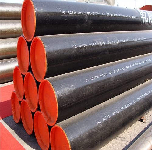
ASME B16.9 does not assign specific PSI ratings directly to fittings. Instead, the fitting is rated to match the straight seamless pipe of the same material and wall thickness. This principle applies across major design codes, including ASME B31.1 for power piping, B31.3 for process piping, and B31.5 for refrigeration piping. If a seamless pipe can handle the operational pressure and temperature, a matching B16.9 fitting will perform equally well. You must determine the pipe's capacity to establish the fitting's rating. This matching principle simplifies procurement but places heavy emphasis on accurate pipe schedule calculations.
Calculating minimum wall thickness requires a strict formulaic approach. You must determine the required schedule based on design pressure, operating temperature, and material allowable stress limits. The standard Barlow's formula, modified by ASME code requirements, dictates the minimum required thickness. You must account for the pipe's outside diameter, the internal design pressure, the allowable stress at the design temperature, and the longitudinal weld joint quality factor. This calculation provides the baseline thickness before adding any allowances. Engineers use specialized software to run these calculations, but understanding the underlying math is essential for field verification.
Factoring in corrosion and erosion allowances is critical for long-term safety. You must adjust baseline thickness calculations to account for operational degradation over time. ASME codes often mandate a 0.05-inch allowance threshold for smaller piping diameters under one inch. Larger allowances are necessary for erosive slurry lines or highly corrosive chemical services. You add this allowance to the calculated minimum wall thickness to determine the final required nominal thickness. This ensures the fitting maintains its pressure rating even after years of internal material loss. Plant operators track this degradation using ultrasonic thickness testing during routine turnarounds.
Temperature derating factors directly impact the maximum allowable working pressure. Material strength degrades significantly at elevated temperatures. Engineers must apply derating factors to calculate the safe operating limits. As the temperature increases, the allowable stress value of the material decreases. You must consult the specific material property tables in the ASME B31 codes to find the correct allowable stress at your exact design temperature. Failing to apply these derating factors leads to catastrophic rupture under thermal load. You must always design for the maximum anticipated upset temperature, not just the normal operating baseline.
ASME B31.3 Allowable Stress Examples for A234 WPB (Simplified for Reference)
Operating Temperature (°F)
Allowable Stress (ksi)
Derating Impact
-20 to 400
20.0
Baseline Strength
500
18.9
Minor Reduction
600
17.3
Moderate Reduction
700
14.3
Significant Reduction
800
10.8
Severe Reduction
Material Selection for Extreme Operating Conditions
Standard components like the carbon steel elbow fitting dominate general industrial applications. Materials conforming to ASTM A234 WPB or WPC offer excellent weldability and structural strength. You must define their optimal temperature windows carefully. These carbon steel grades perform reliably between -20°F and 800°F. Pushing these materials beyond specific thermal limits introduces severe risks. Operating above 800°F for prolonged periods causes graphitization, where the carbon structure weakens. Operating below -20°F introduces the risk of brittle fracture under impact loading. Field inspectors look for specific material stamps to verify the correct grade before welding begins.
Alloy and stainless steel alternatives become necessary when operating outside carbon steel limits. You must transition to ASTM A403 stainless steel grades, such as 304L or 316L, for highly corrosive or cryogenic environments. Stainless steel maintains exceptional toughness at extremely low temperatures. For high-heat applications, Chrome-Moly alloys like ASTM A234 WP11, WP22, or WP91 are required. These alloys resist creep deformation and oxidation at temperatures exceeding 1000°F. Selecting the right alloy prevents premature failure in severe service conditions. Welders must use specific filler metals and pre-heat procedures when working with these advanced alloys.
The rule of material compatibility governs all fitting selections. You must match the fitting's metallurgical properties to the connecting pipe. This matching ensures uniform thermal expansion rates across the joint. Mismatched materials expand at different rates, creating massive shear stresses at the weld seam during thermal cycling. Furthermore, matching materials ensures optimal weldability and prevents galvanic corrosion. Joining dissimilar metals, such as carbon steel to stainless steel, creates a galvanic cell in the presence of an electrolyte, rapidly destroying the less noble metal. You must use dielectric isolation kits if dissimilar metals must be joined in a piping system.
Designing a High Pressure Pipe Joint: Structural Considerations
Directional changes and branch connections inherently create stress multipliers within the piping system. Elbows and tees disrupt the linear flow of stress, concentrating forces at specific geometric points. Engineers use Stress Intensification Factors (SIF) to account for these multipliers. You must apply the correct SIF when verifying the pressure rating of a high pressure pipe joint. The SIF modifies the calculated stress to reflect the actual physical conditions at the fitting. Failure to apply SIFs results in severely under-designed joints that will fail under operational loads. Piping stress analysis software automatically calculates these factors based on the fitting geometry.
Managing thermal expansion requires careful consideration of fitting geometry. High-temperature systems experience significant thermal growth. The piping layout must accommodate this expansion without compromising the weld seams. Expansion loops utilize elbows to absorb thermal movement through controlled bending. The fittings in these loops experience high bending moments. You must ensure the selected schedule and material can withstand these cyclical bending forces alongside the internal pressure. Proper pipe support placement is just as critical as the fitting selection in managing these thermal loads.
Beveling and joint geometry dictate the quality of the final weld. Standard end preparations are required to achieve full-penetration welds. ASME B16.25 specifies the exact bevel angles, typically 37.5 degrees, and root face dimensions for butt weld fittings. Proper beveling ensures the welder can achieve complete fusion through the entire wall thickness. Incomplete penetration creates a severe stress riser and a trap for corrosive fluids, drastically reducing the joint's pressure capacity. Field crews often use specialized beveling machines to prep pipe ends on-site to match the factory-beveled fittings.
Spool fabrication and alignment tolerances impact the final structural integrity. The physical realities of piping spool fabrication introduce imperfections. Internal mismatch, known as "high-low," occurs when the inside diameters of the pipe and fitting do not perfectly align. This misalignment creates stress concentrations and reduces joint efficiency. Strict adherence to alignment tolerances is mandatory. Fitters must carefully measure and adjust the joint before tack welding to minimize high-low and ensure a uniform root pass. You must reject any fit-up that exceeds the code-allowable high-low limits.
Implementation Risks and Quality Assurance
Non-Destructive Testing (NDT) requirements verify the integrity of the weld and the fitting itself before commissioning. Radiography (RT) and Ultrasonic Testing (UT) inspect the internal volume of the weld for porosity, slag inclusion, and lack of fusion. Dye Penetrant (PT) and Magnetic Particle (MT) testing detect surface-breaking defects. You must specify the appropriate NDT methods based on the service fluid and design code requirements. High-pressure systems often require 100% volumetric inspection of all butt welds. Inspectors must be certified to ASNT Level II or III to interpret the test results accurately.
Procurement pitfalls threaten system safety. The global supply chain contains counterfeit materials and out-of-tolerance fittings. You must address these risks aggressively. Audit suppliers for ISO certifications and strict adherence to ASME standards. Verify that the supplier maintains a robust quality management system. Inspect incoming fittings for dimensional accuracy, proper markings, and correct end preparations. Reject any components that deviate from the specified tolerances. A rigorous receiving inspection program is your first line of defense against substandard materials entering the facility.
Material traceability is a critical defense against component failure. You must review Mill Test Reports (MTRs) for every fitting prior to acceptance. The MTR confirms the heat number, chemical composition, heat treatment conditions, and mechanical properties. Cross-reference the MTR data with the requirements of the specified ASTM material grade. Ensure the yield and tensile strengths meet the minimum code requirements. Without verified MTRs, you cannot guarantee the fitting will perform safely under pressure. You must maintain these records in the facility's permanent turnover package for future reference.
Performance Trade-offs in Fitting Selection
Selecting high-grade fittings and utilizing skilled welding labor requires significant upfront investment. However, this initial commitment yields substantial long-term operational reliability. Butt weld systems achieve zero maintenance regarding leak prevention when installed correctly. The continuous welded structure eliminates the need for retorquing bolts or replacing gaskets. This extended lifecycle prevents costly unplanned outages and maintains continuous production in critical process facilities. You must weigh the immediate material costs against the operational security provided by a fully welded system.
Engineers must know when to over-specify components. It is often structurally viable to specify a heavier schedule fitting than mathematically required by the baseline pressure calculations. Highly erosive slurry lines degrade standard wall thicknesses rapidly. Specifying a heavier schedule provides a sacrificial layer of material, extending the operational life of the fitting. High-wear areas, such as the outer radius of elbows in high-velocity gas lines, also benefit from increased wall thickness to combat erosion-corrosion mechanisms. You must analyze the specific fluid dynamics of the system to identify these high-wear zones.
Conclusion
Selecting the right fitting is an exact engineering discipline governed by material matching, precise wall thickness calculations, and strict adherence to ASME codes. You must evaluate the operational parameters rigorously to ensure the piping infrastructure maintains absolute integrity under stress.
Define the exact pressure and temperature parameters for the specific piping system.
Calculate the required pipe schedule using Barlow's formula and applicable ASME code allowances.
Match the fitting material grade and schedule perfectly to the connecting seamless pipe.
Verify supplier Mill Test Reports and mandate appropriate Non-Destructive Testing.
Consult certified piping engineers for complex Stress Intensification Factor calculations.
FAQ
Q: How do you determine the pressure rating of butt weld pipe fittings?
A: Butt weld fittings do not have a standalone PSI rating. Per ASME B16.9, their pressure rating matches the rating of a seamless straight pipe of the same material grade and wall thickness, calculated using the applicable ASME B31 design code.
Q: Can you weld a higher schedule fitting to a lower schedule pipe?
A: Yes, but it requires proper transition machining. You must taper bore the thicker fitting's internal diameter to match the thinner pipe's internal diameter. This prevents severe internal misalignment (high-low) and eliminates dangerous stress concentrations at the weld root.
Q: What is the maximum operating temperature for a carbon steel elbow fitting?
A: Standard carbon steel fittings (like ASTM A234 WPB) are generally limited to 800°F. Operating above this temperature causes graphitization, which severely weakens the steel's structural integrity. Higher temperatures require alloy steels.
Q: How does corrosion allowance impact the selection of a high pressure pipe joint?
A: Corrosion allowance is added to the calculated minimum required wall thickness. This ensures the fitting retains enough structural material to hold the design pressure even after years of internal degradation from corrosive fluids.
Q: Why are butt weld fittings preferred over socket welds for high-pressure systems?
A: Butt welds provide a continuous, full-penetration joint with a smooth internal surface. Socket welds create a crevice at the pipe insertion point, which traps corrosive fluids and acts as a stress riser, making them unsuitable for high-pressure or high-fatigue service.
Q: What documentation is legally required to verify the quality of industrial pipe fittings?
A: Material Test Reports (MTRs) are mandatory. These documents verify the specific heat number, chemical composition, mechanical properties, and heat treatment of the fitting, proving compliance with the specified ASTM material standards.
Q: How does internal misalignment (high-low) affect the fatigue life of welded piping connections?
A: Internal misalignment creates a sharp geometric discontinuity at the weld root. This acts as a severe stress multiplier. Under cyclic loading or thermal expansion, this stress concentration rapidly initiates fatigue cracks, leading to premature joint failure.
Our forged threaded flanges have undergone strict quality control and testing, with excellent strength and reliability, and can withstand high pressure and harsh working environments.
CONTACT US
Phone:+86-13832718182 Email: sales@czweiheng.com WhatsApp:+86-13832718182 Add:East of Construction Machinery Factory, Yanshan County, Cangzhou, Hebei China