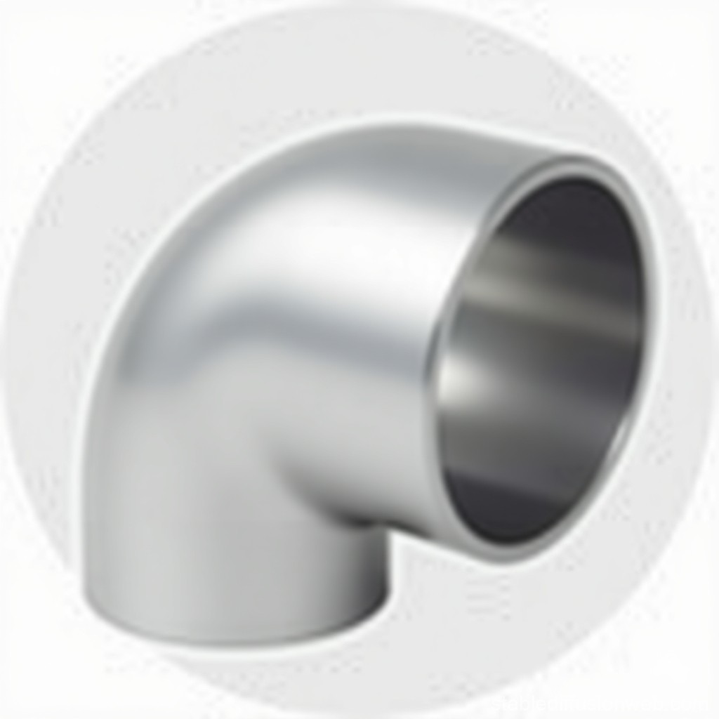
Industrial piping systems operate under immense physical and chemical demands. Within these networks, directional changes represent the most vulnerable points for mechanical stress, pressure drops, and accelerated wear. Straight pipe runs distribute forces evenly, but any directional shift forces the fluid to change momentum, transferring significant kinetic energy directly into the fitting walls. This dynamic makes the integrity of these junctions critical to the entire operation.
Procuring a high-grade stainless steel elbow is only half the equation. Improper installation routinely compromises system integrity, leading to premature failure, hidden leaks, and costly unplanned downtime. Even premium metallurgy cannot compensate for substandard installation practices.
A rigorous, standard-compliant installation framework is an absolute necessity. You must manage mechanical, thermal, and metallurgical factors during installation to guarantee long-term performance. This guide evaluates the critical variables that dictate the lifespan and reliability of your piping directional changes, providing actionable strategies to protect your infrastructure.
Alignment and Fit-Up Dictate Lifespan: Forced alignment (cold springing) introduces residual stresses that accelerate stress corrosion cracking (SCC) and mechanical fatigue.
Welding Execution is Non-Negotiable: Improper heat input and inadequate back-purging degrade the passive layer, instantly compromising the component's corrosion resistance.
Flow Dynamics Require Precision: The orientation and internal weld quality of a stainless flow direction fitting directly impact turbulence, cavitation, and erosion rates.
Environmental Isolation is Critical: Cross-contamination from carbon steel tools during installation or improper handling will cause localized pitting, regardless of the stainless grade.
Operating Atmosphere Interacts with Installation Quality: Operating temperatures combined with oxidizing or reducing environments will rapidly exploit any minor metallurgical or mechanical defect introduced during fit-up.
The Role of Directional Changes in System Integrity
Problem Framing and Success Criteria
Baseline expectations for piping longevity demand decades of leak-free service under continuous operation. Fittings bear the brunt of kinetic energy, pressure fluctuations, and thermal cycling compared to straight pipe runs. When fluid hits an elbow, the velocity profile shifts drastically. This creates areas of high pressure on the outer wall and low pressure on the inner wall. Installation must account for these forces to prevent premature wall thinning and fatigue. Field engineers know that a poorly installed fitting will fail years before the straight pipe connected to it. You have to treat every directional change as a highly engineered stress point rather than just another piece of pipe.
Success in piping installation means achieving a joint that matches the base metal in strength, corrosion resistance, and flow characteristics. Anything less is a failure waiting to happen. You need to look at the entire system dynamics, including pump discharge velocities, valve placements, and thermal expansion loops. The elbow is the focal point where all these systemic forces converge. If your installation team does not understand the fluid dynamics at play, they will make decisions during fit-up that compromise the entire line.
Evaluating Stress Concentration
The geometry of an elbow inherently creates stress concentration zones. The intrados (inner curve) experiences compressive stress during thermal expansion. The extrados (outer curve) handles tensile stress and maximum fluid impact. If the installation introduces additional mechanical loads, these natural stress points become failure initiation sites. Proper support and alignment ensure the fitting only handles the stresses it was engineered to withstand. You cannot use the elbow as a structural support for the rest of the piping system.
When evaluating stress, you must also consider the vibration transmitted from rotating equipment. Pumps and compressors send high-frequency vibrations down the line. The elbow, due to its mass and geometry, often acts as a node where these vibrations amplify. Installing proper isolation supports and ensuring the weld joint is free of defects are the only ways to prevent fatigue cracking at the toe of the weld. Every millimeter of misalignment during fit-up exponentially increases the stress concentration under operating conditions.
Pre-Installation Handling and Material Preparation
Preventing Iron Contamination
Strict segregation protocols are mandatory when handling stainless steel components. Never use carbon steel grinding wheels, wire brushes, or lifting straps on these fittings. Cross-contamination occurs when embedded free iron transfers to the stainless surface. This free iron prevents the formation of the chromium oxide passive layer. Once exposed to moisture, the embedded iron initiates rapid localized rusting on a corrosion resistant elbow, leading to deep pitting.
To ensure absolute material purity on the job site, follow these specific steps:
Establish a dedicated stainless steel fabrication area, physically separated from any carbon steel work.
Issue specific, color-coded tools (grinders, files, brushes) that are only used on stainless alloys.
Use nylon slings or protective polyurethane covers on forklift tines when moving fittings.
Inspect all workbenches and pipe stands, covering them with clean cardboard or stainless steel sheet before placing fittings on them.
Conduct regular ferroxyl testing on the shop floor to detect invisible free iron contamination before welding begins.
Environmental Storage Controls
Dry, temperature-controlled storage prior to installation is essential. Storing fittings outdoors or on dirt floors exposes them to ambient industrial moisture and airborne chemical agents. Chlorides from coastal air or industrial fallout can compromise the protective passive film before the joint is even welded. Keep components in their original packaging, elevated off the ground, and indoors until the exact moment of fit-up. A fitting left exposed to the elements for even a few days can develop micro-pitting that will act as a stress riser once the system is pressurized.
If indoor storage is impossible, you must shrink-wrap the fittings and place desiccant packs inside the wrapping. Cap the ends of the elbows to prevent debris, rodents, and moisture from entering the internal diameter. The internal surface is often more critical than the external surface, especially in high-purity or sanitary applications. Any dirt or moisture that gets inside will cause massive problems during the welding purge process, leading to porosity and rejected welds.
Surface Preparation and Cutting Tolerances
Joint preparation dictates weld quality. Requirements for square, burr-free cuts must be strictly enforced. Improper beveling directly impacts weld penetration and internal flow disruption. If the bevel angle is too narrow, the welder cannot achieve full root penetration. If the root face is uneven, the resulting weld will have internal protrusions that disrupt fluid dynamics and create traps for corrosive agents. You need to use dedicated pipe facing machines rather than hand grinders to achieve the necessary tolerances.
Preparation Parameter
Standard Requirement
Impact of Deviation
Bevel Angle
37.5 degrees (± 2.5)
Lack of fusion or excessive heat input required.
Root Face (Land)
1.6mm (1/16 inch)
Burn-through or incomplete root penetration.
Root Gap
2.4mm to 3.2mm
Excessive internal reinforcement or suck-back.
Surface Cleanliness
Wiped with acetone
Porosity and carbon pickup in the weld pool.
Alignment, Fit-Up, and Mechanical Stress Mitigation
Managing Dimensional Tolerances
Manufacturing tolerances such as ovality and wall thickness variations are realities in any process piping elbow. You must manage these variations during fit-up without compromising the joint. Use specialized alignment clamps to bring the pipe and fitting into concentricity. Never use excessive force to correct ovality. High-low mismatch at the weld joint must be minimized through careful rotation of the fitting or controlled grinding of the thicker wall to match the thinner wall. The ASME B31.3 code strictly limits the allowable internal mismatch, and exceeding it guarantees a stress riser.
When dealing with large diameter thin-wall fittings, ovality becomes a major headache. You cannot just beat the fitting into shape with a deadblow hammer. You have to use chain clamps with independent jacking screws to gently round out the pipe and the fitting simultaneously. Tack welding must be done symmetrically—top, bottom, left, right—to prevent the joint from pulling out of alignment as the tack welds cool and shrink. Rushing the fit-up phase is the number one cause of rejected welds and long-term mechanical failures.
The Dangers of Cold Springing
Cold springing involves forcing misaligned pipes into an elbow to close a gap before welding. This practice induces permanent residual tensile stress into the piping system. Residual stress correlates directly with premature failure modes. In high-temperature environments or chloride-rich media, these locked-in stresses trigger Chloride Stress Corrosion Cracking (CSCC). The pipe must fit naturally into the joint without external mechanical coercion. If you have to use a come-along or a chain fall to pull the pipe to the fitting, your spool dimensions are wrong. Cut it, re-prep it, and do it right.
The insidious nature of cold springing is that the weld might pass initial hydrostatic testing and radiographic inspection. The joint looks fine on day one. However, the constant residual stress acts like a stretched rubber band. As the system undergoes thermal cycling, that stress amplifies. Within months or a few years, microscopic cracks initiate at the heat-affected zone and propagate through the wall thickness. You end up with a catastrophic failure that could have been prevented by spending an extra hour correcting the spool dimensions during fit-up.
Welding and Joining Methodologies
Heat Input and Sensitization Risks
Welding introduces extreme temperatures that alter the metal's microstructure. The Heat Affected Zone (HAZ) is particularly vulnerable to carbide precipitation, known as sensitization, if heat input is not strictly controlled. When chromium binds with carbon at high temperatures, it leaves the surrounding grain boundaries depleted of chromium and susceptible to intergranular corrosion. Gas Tungsten Arc Welding (GTAW/TIG) offers superior heat control and weld purity compared to Shielded Metal Arc Welding (SMAW), making it the preferred method for critical stainless joints.
Controlling interpass temperature is just as important as controlling the initial heat input. You cannot run pass after pass on a stainless joint without letting it cool. The maximum interpass temperature should generally not exceed 150°C (300°F). Use temperature indicating crayons or digital pyrometers to verify the metal has cooled sufficiently before striking the arc again. If you let the joint get too hot, you are baking the chromium out of the matrix, and no amount of post-weld passivation will fully restore the lost corrosion resistance.
Purging and Shielding Gas Requirements
Argon back-purging is an absolute necessity to prevent severe oxidation on the internal diameter of the weld. When molten stainless steel contacts atmospheric oxygen, it forms a heavy, porous oxide layer commonly called "sugaring." This internal oxidation creates severe turbulence. Furthermore, the porous structure acts as an initiation site for crevice corrosion and harbors bacteria in sanitary applications. The internal oxygen level must be monitored and kept below 50 ppm before striking an arc. You cannot guess the purge quality; you must use a calibrated oxygen analyzer.
Setting up a proper purge requires attention to detail. You need purge dams that seal tightly against the internal walls without leaving adhesive residue. The argon must enter at the lowest point and vent at the highest point, as argon is heavier than air. The flow rate must be high enough to displace the oxygen but low enough to avoid creating internal pressure that blows out the molten root pass. A standard practice is to tape the joint with aluminum tape, poking a small hole to allow the gas to escape, and peeling the tape back incrementally as the welder progresses around the pipe.
Managing Flow Dynamics and Internal Topography
Optimizing the Fitting Internals
The internal topography of a stainless flow direction fitting dictates system efficiency. Excessive internal weld reinforcement creates flow restrictions and localized eddies. These eddies trap particulates and accelerate localized wear. In sanitary or high-purity applications, the internal surface roughness (Ra) directly impacts the accumulation of biofilms. Welds must be smooth, fully penetrated, and free of any undercut or excessive convexity. A root pass that hangs down into the flow stream acts like a dam, causing pressure drops and turbulence.
To achieve the optimal internal profile, welders must master the technique of feeding wire into the root gap while maintaining a tight arc length. The purge gas pressure also plays a role; a slight positive pressure inside the pipe helps support the molten puddle, resulting in a flat or slightly concave root profile. After welding, borescope inspections are critical to verify the internal topography. If the root is unacceptable, it must be ground out and repaired, which is a costly and time-consuming process. Getting it right the first time requires highly skilled personnel and strict adherence to the qualified Welding Procedure Specification (WPS).
Cavitation and Erosion-Corrosion Prevention
Improper installation angles or placing an elbow in immediate proximity to valves and pumps exacerbates velocity-induced erosion. When fluid exits a pump, the flow is highly turbulent. If an elbow is placed too close to the discharge, the turbulent fluid violently impacts the extrados, stripping away the passive layer and causing rapid erosion-corrosion. Maintain minimum straight-run distances upstream and downstream of the fitting to allow the flow profile to normalize. You have to give the fluid time to calm down before forcing it to change direction.
Erosion-corrosion is a mechanical-chemical process. The fluid velocity physically scours the protective chromium oxide layer off the metal. Before the metal can repassivate, the corrosive media attacks the bare steel. This cycle repeats rapidly, leading to severe wall thinning on the outer radius of the elbow. To mitigate this, piping designers specify long-radius elbows (1.5D or 3D) instead of short-radius elbows in high-velocity lines. The installation team must ensure these specific fittings are installed in the correct locations and not swapped out for standard fittings due to space constraints.
Environmental and Systemic Installation Variables
Operating Environment Compatibility
The choice of installation location and system design must account for the chemical nature of the process media. A stainless fitting handles oxidizing environments well, as these fluids aid in continuously rebuilding the chromium oxide passive layer. Conversely, reducing environments actively break down the passive layer. In reducing applications, absolute perfection in weld execution and surface finishing is required to prevent rapid material degradation. You cannot leave any arc strikes, spatter, or heat tint on the surface.
The external environment is just as critical as the internal process media. If the piping is installed in a coastal facility or a chemical plant with high airborne chlorides, the exterior of the elbow is under constant attack. Insulation practices also play a major role. If the elbow is insulated, you must ensure the insulation material is chloride-free. Water ingress under the insulation leads to Corrosion Under Insulation (CUI), a hidden and highly destructive failure mode. Proper weatherproofing and the use of protective coatings under the insulation are mandatory field practices.
Thermal Expansion and Anchoring Strategies
Temperature fluctuations cause significant linear expansion in stainless steel piping. If the system is not properly designed, the elbow will absorb this movement. Evaluate the placement of pipe supports, guides, and anchors. Ensure the elbow is not acting as an unintended expansion joint. Forcing a rigid fitting to absorb thermal cycling leads to severe fatigue failure at the weld joints. The piping must be allowed to grow and shrink freely along its axis.
Installation crews must install pipe guides that allow axial movement while restricting lateral movement. Anchors must be placed at specific points to direct the thermal growth into engineered expansion loops or joints. If an anchor is installed incorrectly, or if a guide binds due to misalignment, the thermal forces will transfer directly into the nearest elbow. Stainless steel expands about 50% more than carbon steel, so you cannot use carbon steel expansion calculations or support spacing when installing stainless systems.
Mitigating Galvanic Corrosion at Dissimilar Metal Joints
Connecting stainless steel to carbon steel, copper, or other alloys introduces the risk of galvanic corrosion. The less noble metal will corrode rapidly in the presence of an electrolyte. Mitigation strategies are mandatory at these junctions. Utilize dielectric unions, isolation flanges, and non-conductive gaskets to completely break the electrical continuity between the dissimilar metals. You have to isolate the bolts, the nuts, and the flange faces.
When installing an isolation flange kit, follow these steps:
Inspect the flange faces to ensure they are clean, flat, and free of deep scratches.
Insert the non-conductive central gasket between the flanges.
Place the insulating sleeves over the bolts before inserting them through the flange holes.
Install the insulating washers against the flange face, followed by the steel washers and nuts.
Tighten the bolts in a star pattern using a calibrated torque wrench to prevent crushing the insulating components.
Test the joint with a multimeter to confirm zero electrical continuity across the flange.
Post-Installation Passivation
Welding, grinding, and handling damage the native chromium oxide layer. Post-installation chemical passivation is necessary to restore this protective barrier. Using citric or nitric acid solutions per ASTM A380 or A967 removes surface contaminants and accelerates the formation of a robust passive film. Skipping this step leaves the installation highly vulnerable to immediate flash rusting and long-term localized corrosion. You cannot rely on ambient air to repassivate a heavily worked surface.
The passivation process involves cleaning the surface with an alkaline degreaser to remove cutting fluids and oils. Once clean, the acid solution is applied via spray, circulation, or gel paste for localized weld seams. The acid dissolves free iron and other impurities without attacking the base metal. After the required dwell time, the area must be thoroughly rinsed with deionized water and allowed to dry. Proper safety gear and environmental containment are required when handling these chemicals on the job site.
Conclusion
To ensure lasting performance and protect your infrastructure, take the following actions immediately:
Mandate strict adherence to ASME B31.3 (Process Piping) or equivalent standards in all contractor Service Level Agreements.
Implement mandatory non-destructive testing (NDT), such as radiography or borescope inspections, for all critical directional joints.
Establish a baseline preventative maintenance schedule to monitor for early signs of joint wear, thermal fatigue, or micro-leaks.
Enforce strict tool segregation policies on the job site to eliminate any risk of carbon steel cross-contamination.
FAQ
Q: Does the welding method affect the corrosion resistance of a stainless steel elbow?
A: Yes. Welding methods with high heat input cause carbide precipitation in the Heat Affected Zone. This depletes chromium at the grain boundaries, drastically reducing localized corrosion resistance. TIG welding is preferred for better heat control.
Q: How do you prevent iron contamination during the installation of stainless steel piping?
A: Prevent iron contamination by strictly segregating tools. Never use carbon steel brushes, grinding wheels, or files on stainless steel. Store components away from carbon steel fabrication areas to avoid airborne grinding dust settling on the surfaces.
Q: What is the minimum straight pipe run required before a process piping elbow?
A: Industry best practices recommend a minimum straight pipe run of 5 to 10 times the pipe diameter upstream of the elbow. This allows turbulent flow from pumps or valves to normalize, reducing erosion on the fitting's extrados.
Q: Why is back-purging necessary when welding a stainless flow direction fitting?
A: Back-purging with an inert gas like argon displaces oxygen inside the pipe. If oxygen is present during welding, the internal weld root will heavily oxidize. This creates a porous surface that restricts flow and initiates crevice corrosion.
Q: How does thermal expansion impact the installation of stainless steel elbows?
A: Stainless steel has a high coefficient of thermal expansion. If pipes are rigidly anchored without expansion loops, the elbow absorbs the linear growth. This induces severe mechanical stress and leads to fatigue failure at the weld joints.
Our forged threaded flanges have undergone strict quality control and testing, with excellent strength and reliability, and can withstand high pressure and harsh working environments.
CONTACT US
Phone:+86-13832718182 Email: sales@czweiheng.com WhatsApp:+86-13832718182 Add:East of Construction Machinery Factory, Yanshan County, Cangzhou, Hebei China