Procuring premium-grade materials for pipeline infrastructure solves only half the equation. Catastrophic failures in the field rarely stem from manufacturing defects; they originate from execution errors during installation. Improper handling, joining, and laying processes permanently degrade the baseline mechanical properties of the pipe. Yield strength drops, fracture toughness compromises, and corrosion resistance fails. These errors lead to premature leaks, compliance failures, and severe safety hazards.
A rigorous, standards-compliant installation framework prevents these outcomes. This guide evaluates the specific field variables, joining parameters across plain, threaded, and belled ends, and environmental controls required to maintain structural integrity from delivery to commissioning. Understanding these variables ensures that physical deployment does not compromise engineered specifications.
Joining Protocol Strictness: Heat input and cooling rates during welding directly dictate the integrity of the Heat-Affected Zone (HAZ); strict adherence to a qualified Welding Procedure Specification (WPS) or precise threading protocols is non-negotiable.
Handling and Bending Limits: Exceeding cold bending tolerances or inducing mechanical damage during transport creates stress concentrators that compromise pressure ratings, particularly in smaller diameter (< 6 inches) seamless pipes.
Coating and Cathodic Protection: Installation practices must protect anti-corrosion coatings; even microscopic abrasions during trenching can accelerate localized corrosion, especially in grades with lower baseline corrosion resistance.
Quality Assurance (QA): Continuous Non-Destructive Testing (NDT) and environmental monitoring during installation are mandatory to meet the latest API 5L (46th Edition) and related ASME B31.4/B31.8 safety standards.
The Role of Installation in API 5L Seamless Steel Pipe Integrity
Baseline Mechanical Properties vs. As-Installed Performance
Pipeline deployment demands that factory-tested yield strength, tensile strength, and fracture toughness remain intact post-installation. Steel mills engineer API 5L seamless steel pipe to meet precise metallurgical standards under controlled conditions. The field environment introduces uncontrolled variables. Mechanical stress from lifting, thermal shock from welding, and physical impact from trenching alter the metallurgical structure of the steel.
When a pipe undergoes field welding, the localized thermal cycle changes the grain structure in the Heat-Affected Zone (HAZ). Rapid cooling forms brittle martensite, reducing the pipe's ability to withstand dynamic loads. Improper cold bending stretches the outer radius (extrados) and compresses the inner radius (intrados), causing wall thinning and residual stress. The as-installed performance relies entirely on mitigating these field-induced alterations to keep the pipe within its original design envelope. Engineers must account for the Bauschinger effect, where steel subjected to cold deformation exhibits a lowered yield strength when stress is applied in the opposite direction.
Success Criteria for High Strength Line Pipe Deployment
Evaluating a successful installation requires measuring specific physical and operational dimensions. The primary success criterion is a zero-defect tolerance in all welds and mechanical joints. Any inclusion, lack of fusion, or porosity acts as a stress multiplier under operational pressure. Preserved coating integrity serves as the second criterion. The anti-corrosion barrier must remain continuous from end to end, including all field joint coatings.
Exact alignment during fit-up minimizes residual stress. Forcing misaligned pipes into position before welding locks permanent bending stresses into the pipeline system. Project managers face a trade-off between installation speed and long-term asset lifecycle costs. Rushing the lowering-in process or skipping environmental controls during welding accelerates the construction schedule but guarantees higher maintenance costs and shorter operational lifespans. Deploying high strength line pipe like X65 or X80 amplifies these requirements, as higher carbon equivalents make the steel more sensitive to handling damage and thermal shock.
Pre-Installation Handling and Storage Factors
Preventing Micro-Fractures and Surface Degradation
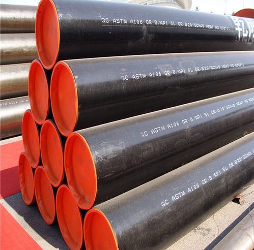
Steel pipe handling requires specialized rigging equipment. Using bare steel cables or chains to lift pipes causes immediate surface damage. These hard materials bite into the steel, creating gouges, dents, and micro-fractures. Under high-pressure operations, these surface imperfections act as stress risers. A seemingly minor gouge concentrates hoop stress, eventually initiating a fatigue crack that propagates through the pipe wall.
Contractors must use wide nylon slings, padded vacuum lifters, or spreader bars equipped with brass or aluminum end hooks. These softer metals prevent gouging the steel bevels. Operators must avoid sudden dynamic loads, such as dropping the pipe onto stockpiles or dragging it across abrasive surfaces. Every physical interaction with the pipe must prioritize surface preservation. Field inspectors should carry pit gauges to measure the depth of any accidental scratches, ensuring they do not exceed the 12.5% wall thickness tolerance allowed by API 5L.
Diameter-Specific Stacking, Transport, and Environmental Shielding
Stacking protocols depend heavily on the pipe's diameter and wall thickness. Excessive stacking heights cause the bottom layers to deform, leading to ovality. Ovality complicates joint fit-up and compromises the structural integrity of the pipeline. Seamless pipes are predominantly utilized in diameters under 150 mm (6 inches). These smaller diameters require specific bundling and cribbing techniques compared to larger welded pipes.
Pipe Diameter (OD)
Wall Thickness (WT)
Maximum Stacking Tiers
Dunnage Requirements
Under 4 inches
Standard (STD)
Up to 8 tiers
Padded timber every 10 feet
4 to 6 inches
Extra Strong (XS)
Up to 6 tiers
Contoured chocks, padded timber
8 to 12 inches
Standard (STD)
Up to 4 tiers
Heavy-duty contoured saddles
Over 12 inches
Double Extra Strong (XXS)
Up to 3 tiers
Engineered steel racks with rubber lining
End-caps prevent internal contamination from moisture, dirt, and vermin. They protect the vulnerable beveled or threaded ends from physical impact. A damaged bevel requires field re-facing, which consumes time and introduces the risk of inconsistent weld preparations. Pipes must be stored on sloped racks to allow water drainage and prevent internal pooling, which can initiate flash rust before the pipe even enters the trench.
Joining Procedures: Welding and End-Type Considerations
End-Type Specific Installation Dynamics
The connection method dictates the mechanical stress distribution across the pipeline network. Different end preparations require distinct installation protocols and tooling.
End Type
Installation Dynamics
Stress Distribution Characteristics
Plain-End
Requires precise beveling (typically 30 degrees) and full-penetration butt welding. Internal or external alignment clamps are mandatory to prevent high-low mismatch.
Provides uniform stress distribution. The weld metal becomes continuous with the base metal, ideal for high-pressure transmission.
Threaded-End
Requires exact torque application using specialized power tongs. API-approved thread compound must be applied to prevent galling and ensure a leak-proof seal.
Stress concentrates at the thread roots. Vulnerable to bending loads and fatigue over time. Limited to lower pressure gathering lines.
Belled-End
Involves slipping the spigot end into the bell. Joined via fillet welding or specialized industrial adhesives depending on the fluid application.
Creates a lap joint. Stress distribution is asymmetrical, making it less suitable for high-pressure gas transmission but acceptable for water or slurry.
Through-the-Flowline (TFL)
Requires extremely tight internal diameter tolerances to allow the passage of TFL maintenance tools. Internal weld root reinforcement must be strictly controlled.
Internal flushness is prioritized. Stress distribution is similar to plain-end but requires higher precision in fit-up and root pass execution.
Heat Input Control and Heat-Affected Zone (HAZ) Management
Welding applies intense localized heat to the steel. Excessive heat input alters the microstructure of pipeline seamless steel pipe. If the heat input is too high, the grain structure coarsens, leading to a loss of yield strength and impact toughness in the HAZ. If the heat input is too low, the rapid cooling rate promotes the formation of hard, brittle microstructures susceptible to hydrogen-induced cracking.
Controlling interpass temperatures during multi-pass welding is mandatory. Welders must allow the joint to cool to a specific temperature range before applying the next pass. This practice ensures consistent mechanical properties throughout the weld volume and prevents cumulative heat buildup from degrading the base metal. Field inspectors use digital pyrometers or temperature-indicating crayons to verify the steel temperature before the welder strikes an arc.
Consumable Selection for High Strength Line Pipe
The strength of the weld must match or exceed the strength of the base metal. Selecting the correct welding consumables requires matching the chemical composition and mechanical properties of the specific API 5L grade.
Grade B and X42: Cellulosic electrodes (like E6010) provide deep penetration and fast travel speeds for the root pass.
Grade X52 and X60: A combination of cellulosic root passes and low-hydrogen fill passes (like E7018) balances speed with mechanical integrity.
Grade X65 and X80: Strict low-hydrogen processes are required. Automated Gas Metal Arc Welding (GMAW) or Flux-Cored Arc Welding (FCAW) using specialized high-tensile wire prevents under-matching the base metal strength.
Using mismatched consumables results in under-matched welds, creating weak points that will fail under operational pressure. Consumables must be stored in heated ovens on-site to prevent moisture absorption, which directly introduces hydrogen into the weld pool.
Pre-Heating and Post-Weld Heat Treatment (PWHT) Requirements
Environmental and metallurgical factors trigger the need for pre-heating. Low ambient temperatures accelerate the cooling rate of the weld pool, increasing the risk of cracking. High carbon equivalent (CE) in the steel chemistry also increases hardenability. Pre-heating the joint with induction coils or propane torches slows the cooling rate, allowing hydrogen to diffuse out of the weld metal and preventing brittle microstructures.
Post-Weld Heat Treatment (PWHT) mitigates residual welding stresses. In thicker-walled pipes, the thermal contraction of the weld metal pulls against the rigid base metal, locking in massive internal stresses. PWHT involves heating the completed weld to a specific temperature (often between 600°C and 650°C), holding it there to allow the steel to relax, and then cooling it slowly. This process restores ductility and reduces the risk of stress corrosion cracking in sour gas environments.
Bending, Alignment, and Trenching Dynamics
Cold Bending Limits and Yield Strength Preservation
Pipelines rarely run in straight lines. Field cold bending allows the pipe to conform to the topography of the trench. Bending steel past its elastic limit permanently deforms the pipe wall. Standards define maximum allowable bending radii based on the pipe's diameter, wall thickness, and yield strength. ASME B31.8 dictates that field bends must not exceed 1.5 degrees of deflection per pipe diameter length.
Exceeding these limits causes the pipe to buckle, wrinkle on the intrados, or thin excessively on the extrados. Wrinkles disrupt internal flow, create severe stress concentrators, and interfere with internal inspection tools (smart pigs). Field cold bending utilizes hydraulic bending machines with internal pneumatic mandrels to support the pipe wall. This differs significantly from factory induction bending, which uses heat to form tight-radius bends without altering the pipe's structural integrity.
Bedding, Backfilling, and Soil-Pipe Interaction
The trench bottom must provide continuous, uniform support for the pipeline. Uneven bedding causes spanning, where the pipe bridges a gap between two high points. Once the pipeline is pressurized and loaded with the weight of the backfill, spanning induces severe bending stresses that can exceed the pipe's yield strength.
Contractors must prepare the trench bottom with fine, rock-free soil or sand bags. Backfilling requires equal care. Dropping heavy, frozen clods or sharp rocks onto the pipe punctures the anti-corrosion coating. The initial backfill layer (padding) must consist of screened material to protect the pipe. In rocky terrain, contractors wrap the pipe in a heavy-duty rock shield before pushing the main backfill into the trench.
Managing Cathodic Protection and Grade-Specific Coating Integrity
The lowering-in phase presents the highest risk to coating integrity. Sidebooms must lift and lower the pipe string in unison to prevent excessive bending and scraping against the trench walls. Before lowering, inspectors use holiday detectors (jeeps) to scan the entire pipe for microscopic coating voids. The voltage of the holiday detector must be calibrated precisely to the thickness of the factory coating (e.g., Fusion Bonded Epoxy or 3LPE) to avoid burning through the material.
Field Joint Coatings (FJC) protect the welded areas. These areas are grit-blasted to a near-white metal finish (Sa 2.5) and coated with liquid epoxy or heat-shrink sleeves. Because corrosion resistance varies across different API 5L grades, FJC strictness must calibrate to the specific grade's vulnerability. High-strength grades exhibit higher susceptibility to environmental cracking, demanding flawless FJC application.
Installation practices directly affect the calibration of cathodic protection (CP) systems. The CP system applies a direct current to the pipeline to suppress corrosion at any coating holidays. If the installation process causes excessive coating damage, the CP system will drain its current rapidly, failing to protect the pipeline adequately and requiring premature replacement of sacrificial anodes.
Environmental and Site-Specific Installation Variables
Temperature Fluctuations and Thermal Expansion
Steel expands and contracts with temperature changes. Installing pipelines in extreme ambient temperatures complicates the management of thermal stresses. A pipe welded during the heat of the day will contract significantly when the temperature drops at night. If the pipe is locked into the trench via backfilling while fully expanded, the subsequent contraction generates massive tensile stresses.
Engineers calculate specific tie-in temperature ranges based on the pipe's coefficient of thermal expansion. Contractors leave sections of the pipeline un-backfilled until the ambient temperature reaches this target range. Tying-in the final connections at the correct temperature minimizes the operational thermal stresses the pipeline will experience over its lifespan. In permafrost regions, pipelines are often installed on elevated supports to prevent the heat of the fluid from melting the ground and causing subsidence.
Moisture, Contaminants, and Early-Stage Corrosion Mitigation
Moisture is the enemy of welding and coating operations. Welding in high-humidity or rainy conditions introduces hydrogen into the weld pool. Hydrogen-induced cracking (HIC) may not appear until days after the weld is completed, making it a dangerous and hidden defect. Moisture also prevents field joint coatings from adhering properly to the steel surface.
Mitigation strategies require strict environmental controls. Contractors must deploy environmental shelters (welding habitats) to protect the joint from rain and wind. Dew-point monitoring is mandatory before abrasive blasting and coating. The steel surface temperature must remain at least 3°C (5°F) above the dew point to prevent invisible condensation from forming under the coating. Failure to observe this rule guarantees coating delamination within the first few years of operation.
Quality Assurance and Non-Destructive Testing (NDT)
Validating Oil and Gas Transmission Pipe Installations
Visual inspection cannot confirm the internal integrity of a weld. Validating oil and gas transmission pipe installations requires comprehensive Non-Destructive Testing (NDT) before the pipe is buried. Different NDT methods detect different types of flaws.
Radiographic Testing (RT): Uses X-rays or gamma rays to produce an image of the weld interior on film or digital sensors. Excellent for detecting volumetric defects like porosity, slag inclusions, and lack of penetration.
Ultrasonic Testing (UT): Uses high-frequency sound waves to detect internal flaws. Phased Array UT (PAUT) provides highly accurate depth and sizing data for planar defects like cracks and lack of fusion, which RT might miss depending on the angle.
Magnetic Particle Inspection (MPI): Detects surface and near-surface discontinuities in ferromagnetic materials. Used primarily for inspecting fillet welds, repair excavations, and detecting surface cracks.
Liquid Penetrant Testing (PT): Used on non-magnetic components or to verify the removal of surface defects before weld repair.
Hydrostatic testing serves as the final validation of installation quality. After backfilling, the pipeline is filled with water and pressurized to a level exceeding its maximum allowable operating pressure (MAOP), typically 1.25 to 1.5 times the MAOP. The pressure is held for a minimum of 8 hours. This test proves the system's pressure containment capability and verifies that no critical defects remain.
API 5L (46th Edition) and Regulatory Compliance Checklists
Contractors must execute installations in strict accordance with the latest API 5L (46th Edition) specifications, ASME B31.4 (liquid) or B31.8 (gas) codes, and local regulatory requirements. Compliance requires a robust framework of documentation and traceability.
Every pipe joint, heat number, weld, and NDT report must be tracked and mapped. If a defect is found years later, operators must be able to trace that specific weld back to the exact welder, the specific batch of consumables, and the environmental conditions recorded on that day. Quality assurance proves that the installation process remained under strict control from start to finish. Inspectors must sign off on daily welding logs, coating adhesion tests, and trench bottom inspections before backfilling can commence.
Conclusion
The operational reliability of API 5L seamless steel pipe is inextricably linked to the precision of its installation. Superior metallurgy cannot compensate for poor field execution. When handling damages the surface, welding alters the microstructure, or trenching compromises the coating, the pipeline's engineered safety margins vanish. Protecting the asset requires treating the installation phase as a highly controlled manufacturing process executed in an uncontrolled environment.
Procurement and project managers must evaluate installation contractors based on their documented Welding Procedure Specifications, their internal NDT capabilities, and their historical adherence to the latest API and ASME standards. Selecting a contractor based solely on laying speed introduces unacceptable long-term risks.
To ensure field integrity, execute the following next steps:
Initiate a comprehensive pre-installation audit of the contractor's handling equipment, lifting protocols, and storage facilities.
Consult with metallurgical engineers to define grade-specific joining requirements, including exact pre-heating and interpass temperature parameters.
Establish a strict QA/QC protocol on the project site, mandating 100% NDT on all high-pressure transmission welds before lowering-in.
Implement continuous environmental monitoring for dew point and ambient temperature to dictate safe windows for welding and coating applications.
FAQ
Q: What is the maximum bending radius for API 5L seamless steel pipe during field installation?
A: The maximum cold bending radius depends on the pipe diameter, wall thickness, and specific yield strength. Standards like ASME B31.8 dictate that field bends must not exceed 1.5 degrees of deflection per pipe diameter length. Exceeding this limit causes buckling, wrinkling, or excessive wall thinning on the extrados.
Q: How do pipe end types (plain, threaded, belled) impact the installation procedures for pipeline seamless steel pipe?
A: Plain ends require precision beveling, alignment clamps, and full-penetration butt welding. Threaded ends demand specialized power tongs for exact torque application and thread compounds to prevent galling. Belled ends involve slipping the spigot into the bell, requiring fillet welding or adhesives, creating an asymmetrical stress distribution.
Q: How does welding heat input affect the performance of high strength line pipe?
A: Excessive heat input coarsens the grain structure in the Heat-Affected Zone (HAZ), reducing yield strength and fracture toughness. Insufficient heat input causes rapid cooling, forming brittle martensite susceptible to hydrogen-induced cracking. Strict adherence to a qualified WPS balances heat input and cooling rates.
Q: Do different API 5L grades (e.g., Grade B vs. X65) require different installation and coating procedures?
A: Yes. Higher grades like X65 or X80 have different carbon equivalents, requiring stricter pre-heating, specialized low-hydrogen consumables, and tighter interpass temperature controls. Higher-strength grades are more susceptible to environmental cracking, demanding rigorous surface preparation and flawless Field Joint Coating (FJC) application.
Q: What are the most common installation-related failures for oil and gas transmission pipe?
A: The most common failures include hydrogen-induced cracking from improper pre-heating or moisture exposure, coating delamination from applying FJC below the dew point, and fatigue cracking initiated by surface gouges caused by improper lifting equipment during the handling phase.
Q: How should API 5L pipes (especially diameters under 6 inches) be stored on-site to prevent degradation?
A: Small diameter seamless pipes must be stored on sloped racks with padded dunnage between layers to prevent metal-to-metal contact and ovality. Stack heights must be strictly limited. End-caps must remain in place to block moisture, debris, and vermin, and to protect the beveled ends.
Q: How do the updates in the API 5L 46th Edition affect field installation and QA requirements?
A: The 46th Edition enforces stricter tolerances on pipe end dimensions, out-of-roundness, and wall thickness variations. This requires contractors to use more precise alignment clamps during fit-up and mandates comprehensive traceability for every heat number, weld, and NDT report to ensure full regulatory compliance.
Our forged threaded flanges have undergone strict quality control and testing, with excellent strength and reliability, and can withstand high pressure and harsh working environments.
CONTACT US
Phone:+86-13832718182 Email: sales@czweiheng.com WhatsApp:+86-13832718182 Add:East of Construction Machinery Factory, Yanshan County, Cangzhou, Hebei China