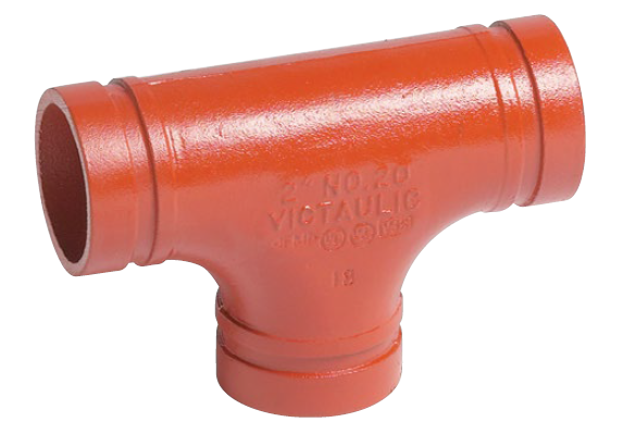
Industrial piping projects demand a strict balance between installation velocity, labor economics, and long-term joint integrity under dynamic operational stresses. Traditional welding requires expensive skilled labor, extensive hot-work permitting, and prolonged downtime. Shifting to mechanical joining methods solves these labor bottlenecks but introduces new failure risks if dimensional tolerances, material compatibilities, and system transitions are not rigorously specified. We see field failures constantly because contractors ignore basic pipe preparation standards. This guide provides a comprehensive framework for evaluating, specifying, and mitigating implementation risks when integrating grooved pipe fittings into industrial and commercial piping systems. You will learn exactly how to match gasket materials to fluid types, control gap tolerances, and eliminate the most common installation defects on the job site.
The choice between roll-grooved and cut-grooved preparation is dictated by pipe schedule, wall thickness, and system pressure requirements.
Elastomeric gasket selection is the most critical variable for system longevity, requiring exact matching to thermal, chemical, and pressure exposures.
Strict adherence to manufacturer gap tolerances, groove dimensions, and torque specifications is mandatory to prevent the most common mechanical joint failures.
While upfront material costs for mechanical joints are higher, they are typically offset by a 30–60% reduction in installation time and the elimination of hot-work protocols.
Core Mechanics of a Mechanical Pipe Coupling System
Understanding the physical mechanics of how pressure-responsive joints operate is necessary to evaluate their suitability for specific industrial applications. Mechanical connections rely on precise physical engagement rather than fused metal. Engineers must understand how components interact under dynamic loads to design resilient pipelines. We evaluate these systems based on three primary components: the pipe end preparation, the housing, and the sealing element.
The Grooved Pipe End: Roll vs. Cut Grooving
Roll grooving involves cold forming a depression into the pipe end using heavy mechanical rollers. This process displaces the pipe material inward without removing any metal. The internal diameter of the pipe decreases slightly at the groove location. Cut grooving removes material via machining to create the required profile, similar to cutting threads into a pipe. Both methods prepare the pipe end to receive the coupling housing, but they apply to different pipe schedules.
Pipe schedule and wall thickness dictate the appropriate grooving method. Standard or heavy-wall pipes, such as Schedule 40 and above, possess enough wall thickness to withstand cut grooving without compromising structural integrity. Thinner-wall pipes, like Schedule 10, require roll grooving. Cutting a groove into thin-wall pipe removes too much material, creating a weak point susceptible to rupture under pressure. Field crews must verify the pipe schedule before setting up the grooving machine.
Grooving directly affects the structural integrity of the pipe end. Adhering strictly to manufacturer specifications ensures the groove dimensions accommodate the coupling keys perfectly. Accurate groove depth and width are non-negotiable parameters. Deviations from these dimensions prevent the housing from seating correctly, leading to joint leaks and catastrophic blowouts. Field crews must measure the "A" dimension (distance from pipe end to groove) and the "B" dimension (groove width) using calibrated tools.
Grooving Method
Process Type
Applicable Pipe Schedules
Impact on Internal Diameter
Roll Grooving
Cold Forming (Displacement)
Schedule 5, 10, standard wall
Slight reduction at groove
Cut Grooving
Machining (Material Removal)
Schedule 40, 80, heavy wall
No change to internal diameter
The Coupling Housing: Rigid vs. Flexible Configurations
The housing keys physically engage the groove to provide end-load resistance. This mechanical grip prevents pipe separation under severe pressure thrusts. Cast ductile iron is the standard material for these housings, providing high tensile strength and impact resistance. The housing also contains the gasket, protecting it from external damage and UV degradation.
Rigid couplings are specified for applications requiring strict linear alignment and support minimization. They clamp tightly around the pipe, providing a rigid connection similar to a flanged or welded joint. The housing pads meet metal-to-metal, gripping the pipe firmly to prevent angular deflection or axial movement. Engineers use rigid couplings in mechanical rooms and long straight runs where pipeline shifting is undesirable.
Flexible couplings are engineered for systems requiring vibration attenuation, seismic stress relief, or thermal expansion accommodation. They allow controlled linear and angular movement. The housing keys are cast with a slightly wider profile than the pipe groove. This intentional clearance allows the pipeline to flex and shift without compromising the internal seal, protecting the pipeline from dynamic stresses.
Rigid Coupling Applications: Pump discharge lines, vertical risers, mechanical equipment rooms, and long straight runs requiring minimal support spacing.
Flexible Coupling Applications: Seismic joints, expansion loops, areas prone to building settlement, and connections near vibrating equipment.
The Elastomeric Gasket: Pressure-Responsive Sealing
The C-shaped elastomeric gasket design creates a pressure-responsive seal. During installation, the gasket stretches slightly over the pipe ends. This interference fit provides an initial seal before the system is pressurized. The gasket bridges the gap between the two pipe ends, isolating the fluid from the external housing.
Internal system pressure reinforces this seal. As fluid or gas fills the pipeline, it enters the C-shaped cavity of the gasket. The internal pressure pushes the sealing lips outward against the pipe exterior and the inner wall of the coupling housing. Higher internal pressure results in a tighter seal. This dynamic sealing mechanism allows the joint to maintain integrity across fluctuating operational pressures.
Strategic Advantages and Operational Trade-offs
Comparing mechanical joining against traditional welding, flanging, and threading is essential to justify specification across different pipe diameters. Project managers must evaluate installation speed, safety compliance, and long-term maintenance requirements. We look at the holistic impact on the construction schedule and facility lifecycle.
Installation Velocity vs. Material Costs
Analyzing the return on investment of a quick connect pipe fitting system requires looking beyond initial purchase prices. Mechanical components carry a higher unit cost than raw steel pipe and welding consumables. However, this upfront expense must be weighed against total installation labor.
Compare the higher unit cost of grooved components against the reduction in skilled labor hours, scaffolding requirements, and specialized equipment. Mechanical joints assemble rapidly using standard hand tools. A two-person crew can install a mechanical joint in a fraction of the time required to weld the same diameter pipe. This drastically reduces overall project timelines and accelerates facility commissioning. Welding a 6-inch Schedule 40 pipe joint can take over an hour of prep, welding, and inspection. Grooving and assembling that same joint takes less than fifteen minutes.
Elimination of Hot Work and Safety Compliance
Removing welding from the site offers immense operational benefits. It eliminates fire watches, toxic fumes, and the need for complex ventilation systems. Facilities handling volatile chemicals or operating in confined spaces benefit significantly from cold joining methods. You do not need to shut down adjacent operations to accommodate a welding crew.
Safety compliance becomes significantly easier to manage. Reduced fire risks translate to lower insurance liabilities and fewer regulatory hurdles during construction. Site managers spend less time securing hot-work permits and more time advancing the critical path of the project. The absence of welding arcs also protects workers from flash burns and exposure to hazardous fumes like hexavalent chromium.
System Maintenance and Retrofitting
Mechanical joints provide a massive lifecycle advantage for systems requiring frequent maintenance, expansion, or component replacement. Welded systems require cutting, grinding, and re-welding to modify the pipeline. This process introduces debris into the system and requires extensive downtime. Draining a welded system, cutting out a valve, and welding in a replacement can take an entire shift.
A mechanical pipe coupling can be disassembled in minutes. Maintenance crews loosen two bolts, remove the housing, and slide the gasket back to access the pipe interior. This allows rapid access to valves, strainers, or damaged pipe sections without cutting or grinding. Facility managers can execute pipeline modifications during short operational windows.
Step-by-Step Specification Framework for Grooved Pipe Fittings
Matching specific fitting configurations to industrial project requirements demands a systematic approach. Engineers must define operational parameters before selecting materials or modeling the system. Guesswork during the specification phase leads to catastrophic failures during commissioning.
Defining System Pressure and Thermal Parameters
Establish baseline operating pressures, surge pressures, and vacuum conditions before selecting any components. Mechanical couplings carry specific pressure ratings based on pipe diameter, wall thickness, and housing design. Engineers must ensure the selected coupling exceeds the maximum anticipated system pressure, including water hammer events. A coupling rated for 300 psi on Schedule 40 pipe might only be rated for 150 psi on Schedule 10 pipe.
Map temperature ranges meticulously to prevent gasket degradation or thermal expansion failures. High-temperature spikes can permanently deform standard elastomers. Continuous exposure to temperatures outside the gasket's rated limits causes the material to harden, crack, and eventually fail. You must account for both the ambient environment and the internal fluid temperature.
Selecting the Right Gasket Material
Provide a decision matrix for standard gasket materials. Selecting the wrong elastomer guarantees premature joint failure. Engineers must cross-reference the system fluid with the manufacturer's chemical compatibility charts. Never assume a gasket suitable for water is suitable for compressed air, as compressor oils will destroy standard water-rated elastomers.
Gasket Material
Color Code
Primary Applications
Temperature Range
EPDM
Green Stripe
Potable water, HVAC, compressed air (oil-free)
-30°F to 230°F
Nitrile (Buna-N)
Orange Stripe
Petroleum products, mineral oils, air with oil vapors
Highlight the risks of chemical incompatibility leading to gasket swelling or embrittlement. Exposing an EPDM gasket to petroleum-based fluids causes the elastomer to swell rapidly. This swelling forces the gasket out of the housing, resulting in immediate joint failure and environmental contamination. We have seen entire mechanical rooms flood because a contractor used EPDM gaskets on a fuel oil line.
Specifying for Specialized Applications
A fire protection groove fitting requires strict regulatory certifications. Engineers must specify components carrying UL listing, FM approval, and NFPA 13 compliance. These certifications verify the components have undergone rigorous testing for fire endurance and pressure retention. You cannot substitute standard commercial fittings into a fire suppression network.
HVAC systems require specific vibration attenuation characteristics to isolate pump noise from the building structure. Mining applications demand high abrasion resistance to handle slurry transport. Wastewater systems require gaskets capable of withstanding corrosive effluents and biological degradation. Each of these environments dictates a specific housing material, coating, and gasket combination.
Integrating with BIM and 3D Modeling
Utilizing manufacturer-provided BIM content is vital for accurate spatial planning and clash detection. Generic pipe models lack the precise dimensional data required to coordinate complex mechanical rooms. Manufacturer-specific Revit families include accurate outside diameters, take-out dimensions, and clearance requirements for bolt tightening. If you model a generic coupling, you will likely find that the actual physical coupling hits a wall or adjacent pipe during installation.
Setting routing preferences and creating combined grooved and threaded pipe types in Revit MEP allows engineers to accurately model real-world system transitions. For example, modeling Schedule 40 steel pipe with grooved mains and threaded branches requires configuring the routing preferences to automatically insert the correct transition fittings. This ensures precise clash detection and generates flawless bills of materials for procurement.
Implementation Realities: Mitigating Risk and Preventing Defects
Addressing common field execution errors is critical to ensure specified systems perform as designed. Even the most robust components will fail if installed incorrectly. We focus heavily on pipe preparation and assembly techniques to eliminate rework.
Managing Pipe Ovality and Dimensional Tolerances
Pipe ovality refers to the deviation of a pipe's cross-section from a perfect circle. Severe ovality prevents the coupling housing from seating properly. When the housing cannot close around an out-of-round pipe, the gasket is left exposed and unsupported. This happens frequently when pipe is mishandled during shipping or stored improperly on site.
Specify acceptable tolerance ranges for pipe diameter and groove depth. Improper grooving remains the primary root cause of gasket failure and system leaks. Field crews must use calibrated Pi tapes to verify the outside diameter and groove dimensions before attempting installation. Rejecting out-of-tolerance pipe ends prevents costly rework during hydro-testing. If the groove is too shallow, the housing keys will not engage. If the groove is too deep, the pipe wall is compromised.
Addressing Pipe End Gap Tolerances
The gap between pipe ends within the coupling housing is a critical design feature, especially for flexible couplings. This gap allows the pipe to expand, contract, and deflect. Installers must set this gap according to the manufacturer's specifications during assembly.
Exceeding manufacturer-specified gap tolerances leads to gasket extrusion, loss of end-load resistance, or complete joint separation under pressure. If the gap is too wide, internal pressure forces the gasket down between the pipe ends, compromising the seal. If the gap is too tight, the system loses its ability to accommodate thermal expansion. Crews must physically measure the gap before tightening the housing bolts.
Preventing Gasket Pinching and Extrusion
Implement mandatory field protocols to prevent installation defects. Proper gasket lubrication is non-negotiable. Applying the manufacturer-approved lubricant to the gasket exterior and sealing lips prevents the elastomer from tearing as the housing clamps down. Using the wrong lubricant, such as a petroleum-based grease on an EPDM gasket, will destroy the elastomer.
Visual inspection of seating ensures the gasket lips are not pinched between the pipe ends. Mindful, alternating tightening of housing bolts prevents uneven torque and housing misalignment. Crews must tighten the nuts evenly, alternating sides, until the housing bolt pads achieve firm metal-to-metal contact. Uneven tightening distorts the housing and compromises the pressure rating of the joint.
Audit your current piping schematics to identify specific zones where mechanical joints can replace welded connections.
Consult with a piping engineer to verify pipe schedules and determine the appropriate grooving method for your application.
Request technical submittals and chemical compatibility charts from shortlisted manufacturers to ensure exact gasket matching.
Verify field installation training programs and require mandatory certification for all site crews handling mechanical systems.
FAQ
Q: What is the difference between rigid and flexible grooved pipe fittings?
A: Rigid couplings clamp tightly to the pipe, preventing movement and maintaining strict linear alignment, similar to a welded joint. Flexible couplings feature a wider key profile, allowing controlled linear and angular movement to accommodate thermal expansion, seismic activity, and vibration attenuation.
Q: Can grooved pipe fittings be used for high-pressure steam systems?
A: Standard elastomeric gaskets are generally not suitable for high-pressure steam due to temperature limitations. However, specific manufacturers offer specialized steam-rated couplings utilizing advanced composite materials or specialized seals designed to withstand the extreme temperatures of steam applications.
Q: How do you prevent leaks in a mechanical pipe coupling?
A: Preventing leaks requires strict adherence to manufacturer groove dimensions, selecting the correct gasket material for the fluid, applying proper lubrication, and ensuring mindful, alternating bolt tightening until the housing pads achieve full metal-to-metal contact.
Q: What pipe schedules are suitable for roll grooving vs. cut grooving?
A: Cut grooving is suitable for standard or heavy-wall pipes (Schedule 40 and above) where removing material will not compromise structural integrity. Roll grooving is required for thinner-wall pipes (Schedule 10) to maintain material thickness, though it can also be used on heavier schedules.
Q: Are grooved fittings approved for underground fire protection systems?
A: Yes, specific grooved fittings are approved for buried applications. They must feature specialized corrosion-resistant coatings, comply with AWWA standards, and carry necessary NFPA approvals and UL/FM certifications specifically rated for underground fire protection service.
Q: How long do elastomeric gaskets in grooved fittings last?
A: When correctly specified for the system's thermal and chemical environment, elastomeric gaskets are designed to last the lifetime of the piping system. Degradation typically only occurs if the gasket is exposed to incompatible chemicals or temperatures exceeding its rated limits.
Q: How do grooved systems transition to threaded components?
A: Transitions are achieved using grooved-to-threaded adapter nipples, specialized transition couplings, or grooved flanges. In MEP software like Revit, engineers configure routing preferences to automatically insert these specific transition families when connecting grooved mains to threaded branch lines.
Our forged threaded flanges have undergone strict quality control and testing, with excellent strength and reliability, and can withstand high pressure and harsh working environments.
CONTACT US
Phone:+86-13832718182 Email: sales@czweiheng.com WhatsApp:+86-13832718182 Add:East of Construction Machinery Factory, Yanshan County, Cangzhou, Hebei China