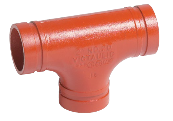
The industrial construction sector is moving rapidly away from traditional hot work and threading. Labor shortages, material costs, and strict project timelines force engineers to seek faster, safer alternatives. Procurement teams and engineers constantly balance upfront component expenses with long-term reliability, safety compliance, and installation speed in high-stakes environments. Specifying Victaulic groove pipe fittings provides a verifiable method to standardize piping installations. This approach reduces jobsite risk, eliminates the need for welding permits, and ensures predictable lifecycle performance when evaluated correctly against project requirements. We see this shift daily on jobsites where schedule compression demands immediate solutions.
Total Installed Cost vs. Material Cost: While individual mechanical couplings may carry a higher unit price than welding consumables, the elimination of hot work, threading prep, and reduction in labor hours typically yields a lower total installed cost.
Productivity through Pre-Assembly: Utilizing patented Installation-Ready™ technology—which arrives pre-assembled with no loose parts—drastically cuts down handling time and minimizes the risk of dropped or lost components on-site.
Material and Media Versatility: Specification requires precise alignment of gasket materials and coupling housings with the specific pipe material (e.g., carbon steel, stainless, ductile iron, aluminum, copper, or HDPE) and the media being transported.
Inherent Flexibility and Vibration Attenuation: Grooved systems can be engineered to accommodate thermal expansion, seismic movement, and pump vibration without requiring specialty expansion joints.
Visual Verification: Quality control is simplified through visual inspection of pad-to-pad bolt pad contact, eliminating the need for X-ray or non-destructive testing (NDT) of joints.
Understanding the Mechanics of a Grooved Piping System
Anatomy of a Mechanical Joint Fitting
A standard mechanical joint fitting relies on three core components. These are the pipe groove, the elastomeric gasket, and the coupling housing with fasteners. The groove is either cold-rolled or machined directly into the pipe ends. The elastomeric gasket wraps around the pipe ends, creating a pressure-responsive seal. This seal tightens as internal system pressure increases. The ductile iron coupling housing encloses the gasket and engages the groove around the entire pipe circumference. Fasteners secure the housing halves together. This mechanical engagement provides self-restraining joint integrity under pressure without relying on threaded connections or welded bonds. Field crews appreciate this simplicity because it removes the variability found in manual welding.
The housing itself is typically cast from ductile iron conforming to ASTM A536. This material provides high tensile strength and impact resistance. The bolts and nuts are usually heat-treated carbon steel, zinc electroplated for corrosion resistance. When you assemble these parts, the housing keys lock into the grooves. This prevents pipe separation under high pressure or axial loads. The gasket design features a C-shaped cross-section. When installed, the gasket lips stretch over the pipe ends. As fluid enters the pipe, it pressurizes the internal cavity of the gasket, forcing the lips tighter against the pipe surface. This creates a leak-tight seal that actually improves as system pressure rises.
Rigid vs. Flexible Couplings
Engineers must choose between rigid and flexible couplings based on system stress analysis and support spacing requirements. Rigid couplings are designed to prevent movement, mimicking the structural behavior of a welded joint. They grip the base of the groove tightly to resist torsional and flexural loads, keeping the piping strictly aligned. Flexible couplings are engineered to allow controlled linear and angular movement. They accommodate thermal expansion, seismic shifts, and structural settlement. Proper specification dictates using rigid couplings for long, straight runs requiring strict support. Flexible couplings are deployed strategically near pumps or expansion loops to absorb vibration and deflection.
Understanding the exact application for each coupling type prevents catastrophic system failures. If you use flexible couplings where rigid ones are required, the pipe may sag or snake under pressure. Conversely, using rigid couplings where flexibility is needed can cause excessive stress on equipment nozzles or pipe supports. We often see this mistake in mechanical rooms where thermal expansion is not properly calculated.
Coupling Type
Primary Function
Typical Applications
Movement Allowance
Rigid Coupling
Prevents pipe movement, maintains alignment
Long straight runs, vertical risers, valve connections
None (mimics welded joint)
Flexible Coupling
Absorbs vibration, allows deflection
Pump connections, expansion loops, seismic zones
Linear and angular movement
Key Evaluation Criteria for Specifying Victaulic Groove Pipe Fittings
Pipe Material Compatibility and Preparation
Specification requirements vary drastically across different pipe materials. A grooved piping system can be adapted for carbon steel, stainless steel, ductile iron, aluminum, copper, and plastics like PVC, CPVC, and HDPE. Each material requires specific coupling housings and groove profiles. Engineers face a trade-off between roll grooving and cut grooving. Roll grooving displaces metal radially and is standard for thin-wall and standard-wall applications. It preserves pipe wall thickness and maintains internal flow dynamics. Cut grooving removes material and is reserved for heavy-wall pipes, internally lined pipes, or highly abrasive applications where roll grooving might damage the internal lining.
When working with stainless steel, you must specify couplings designed specifically for that material to prevent galvanic corrosion. Standard ductile iron housings can cause issues if not properly coated or isolated. For copper tubing, the roll groove profile is shallower to accommodate the softer metal. HDPE pipe requires a completely different coupling design with rows of gripping teeth that bite into the plastic as the housing is tightened. You cannot mix and match these components. Field preparation is equally critical. The pipe ends must be square cut, and the exterior surface from the groove to the pipe end must be smooth and free from indentations, rust, or scale to ensure a proper gasket seal.
Pressure Ratings and Temperature Thresholds
Evaluating coupling pressure ratings against system design pressures is a critical specification step. The maximum allowable working pressure (MAWP) is rarely dictated by the coupling itself. The weakest link is often the pipe wall thickness or schedule. Heavy-duty couplings on Schedule 80 pipe will yield vastly different pressure ratings than standard couplings on Schedule 10 pipe. Temperature limitations must also be strictly defined based on continuous versus intermittent exposure. Industrial fluids operating at extreme temperatures require specific housing alloys and specialized gasket compounds to prevent premature failure.
For example, a standard coupling on 4-inch Schedule 40 carbon steel pipe might be rated for 600 psi. If you drop that to Schedule 10 pipe, the rating might fall to 300 psi. You must consult the manufacturer's submittal data for the exact combination of pipe material, wall thickness, and coupling type. Temperature spikes can also degrade elastomeric gaskets rapidly. If a system normally operates at 180°F but occasionally spikes to 250°F, you must specify a gasket rated for the higher temperature. Ignoring these variables leads to blown gaskets and flooded facilities.
Gasket Selection Based on Media
Gasket specification is the most critical factor in preventing system failure. The elastomeric compound must match the chemical composition of the system media. EPDM gaskets are standard for water and oil-free air systems. Nitrile gaskets are required for petroleum products, hydrocarbons, and oily air. Fluoroelastomer gaskets are specified for harsh oxidizing chemicals and high-temperature environments. Incorrect gasket specification leads to rapid degradation, swelling, or hardening of the elastomer, resulting in catastrophic leaks and system downtime.
We frequently encounter systems where a contractor installed EPDM gaskets on a compressed air line that contained compressor oil carryover. Within months, the EPDM swelled and failed. You must verify the exact chemical makeup of the fluid, including any additives or inhibitors. Color-coding on the gaskets helps field crews identify the material, but the engineer must make the correct initial selection.
Gasket Grade
Material Compound
Color Code
Recommended Media
Temperature Range
Grade E
EPDM
Green Stripe
Hot/Cold Water, Dilute Acids, Oil-Free Air
-30°F to +230°F
Grade T
Nitrile
Orange Stripe
Petroleum Products, Mineral Oils, Oily Air
-20°F to +180°F
Grade O
Fluoroelastomer
Blue Stripe
Oxidizing Acids, Halogenated Hydrocarbons
+20°F to +300°F
Comparing Joining Methods: Grooved vs. Welding, Flanging, and Threading
Total Cost of Installation and Labor Efficiency
Welding requires extensive prep, fit-up, root passes, capping, and mandatory non-destructive testing (NDT). Threading demands heavy machinery, messy thread sealants, and high manual labor. Assembling pre-assembled grooved couplings drastically reduces these labor hours. Reducing loose components like individual bolts, nuts, and gaskets lowers handling overhead and inventory tracking costs on large industrial sites. Eliminating the need for specialized welding equipment, fire watches, and highly skilled, scarce welders significantly accelerates the project schedule.
Consider a typical 6-inch pipe joint. Welding that joint might take a skilled pipefitter two to three hours, factoring in prep and inspection. Grooving the pipe and installing a mechanical coupling takes less than twenty minutes. When you multiply that time savings across thousands of joints on a major industrial project, the labor efficiency becomes massive. You also eliminate the need to drag heavy welding machines, gas cylinders, and protective screens throughout the jobsite. This mobility allows crews to work faster and in tighter spaces.
Jobsite Safety and Risk Mitigation
Safety is a primary driver for mechanical piping specification. Eliminating hot work removes open flames, toxic welding fumes, and arc flash hazards from the jobsite. Avoiding the heavy machinery and repetitive strain associated with threading heavy-wall pipes reduces musculoskeletal injuries among pipefitters. Lowering the jobsite risk profile directly impacts project insurance premiums and reduces the administrative burden of securing daily hot work permits.
Hot work is one of the leading causes of construction site fires. By specifying mechanical joints, you remove the ignition source entirely. You also protect workers from hexavalent chromium exposure when welding stainless steel. The physical toll on workers is significantly reduced. Tightening two bolts with an impact wrench is far less strenuous than manually threading large diameter pipe or holding awkward welding positions for hours.
Maintenance, Expansion, and System Downtime
Mechanical joints offer distinct operational advantages during facility turnarounds or system expansions. Maintenance teams can easily isolate a section, unbolt the couplings, and modify the piping without cutting, grinding, or re-threading. This modularity allows for rapid component replacement, valve integration, or line rerouting, minimizing costly facility downtime.
If a pump needs to be replaced, maintenance crews simply unbolt the flexible couplings, remove the pump, drop the new one in place, and re-tighten the couplings. There is no need to cut pipe or weld new flanges. This turns a multi-day shutdown into a few hours of work. For facilities that undergo frequent process changes, this flexibility is invaluable. You can add tees or branch connections simply by cutting a hole in the pipe and installing a mechanical tee, rather than welding a branch connection.
Application-Specific Specification Requirements
Fire Protection and Fire Sprinkler Pipe Fitting Standards
The regulatory landscape for fire suppression systems mandates strict adherence to safety codes. When specifying a fire sprinkler pipe fitting, engineers must ensure the components carry active FM Approvals and UL Listings. Compliance with NFPA 13 standards is non-negotiable. Grooved systems dominate this sector due to their rapid installation capabilities and reliable pressure performance under emergency conditions.
Fire protection systems sit dormant for years but must perform flawlessly the moment a fire breaks out. The mechanical integrity of grooved joints ensures that the system will hold pressure when the fire pump kicks on. The speed of installation is also critical in commercial construction, where the fire sprinkler system must be installed quickly to allow other trades to finish the ceilings. You will rarely see threaded pipe larger than 2 inches in modern fire protection systems because grooved piping is vastly superior in speed and reliability.
Mining, Slurry, and High-Vibration Environments
Abrasive slurry lines in mining operations require cut-grooved heavy-wall pipe to maximize internal wear life. Roll grooving can create internal protrusions that accelerate localized wear in high-velocity slurry applications. Additionally, grooved joints are specified to isolate vibration from heavy rotating equipment such as pumps, crushers, and grinders. The elastomeric gasket and slight mechanical clearances prevent pipe fatigue and protect sensitive equipment flanges from stress fractures.
In a mining environment, pipe replacement is a constant maintenance task due to abrasion. Mechanical couplings allow crews to rotate the pipe periodically to distribute wear evenly, extending the life of the piping system. The ability to quickly disassemble and reassemble lines in harsh, remote environments without welding equipment is a massive operational advantage. The couplings also absorb the intense vibration generated by slurry pumps, preventing the pipe from shaking itself apart.
HVAC and Commercial Plumbing
Specification parameters for chilled water, heating hot water, and domestic water systems focus heavily on thermal expansion accommodation. Mechanical rooms often feature tight space constraints. Flexible grooved couplings absorb thermal movement without the need for bulky expansion joints or massive pipe loops, saving valuable floor space and simplifying the mechanical layout.
In a high-rise building, the chilled water risers will expand and contract significantly as the system cycles. By placing flexible couplings at specific intervals, the piping system absorbs this movement internally. This eliminates the need for expensive and failure-prone bellows expansion joints. It also reduces the structural load on the building by minimizing the forces exerted on pipe anchors and guides.
Implementation Risks and Mitigation Strategies
Common Installation Errors to Avoid
Despite their simplicity, jobsite failures occur due to out-of-spec groove dimensions. Grooves that are too deep or too shallow compromise the mechanical engagement. Improper gasket lubrication leads to pinched or torn gaskets during assembly. Loose-component couplings pose risks when misplaced bolts or nuts lead to uneven joint tensioning. Mixing and matching different manufacturers' housings and gaskets is a critical error. It immediately voids warranties, invalidates pressure ratings, and nullifies agency approvals.
We see contractors try to save money by buying generic gaskets and putting them in premium housings. This never works. The tolerances are specific to each manufacturer. Another common issue is failing to clean the pipe ends before installing the gasket. Dirt, rust, or loose scale will prevent the gasket from sealing properly, leading to slow leaks. Proper lubrication is also non-negotiable. Without it, the gasket can roll or pinch as the housing is tightened.
Quality Control and Inspection Protocols
Standard inspection procedures for grooved systems are highly visual. Inspectors verify metal-to-metal (pad-to-pad) contact at the bolt pads. Unlike flanged connections, standard grooved installations do not require specialized torque wrenches. To mitigate installation risks, engineers should specify mandatory contractor training sessions prior to project commencement to ensure all crews understand groove measurement and proper assembly techniques.
Verify the pipe material and schedule match the approved submittals.
Measure the groove diameter and depth using a specialized pi-tape to ensure it falls within the manufacturer's tolerances.
Inspect the pipe ends for cleanliness, ensuring no deep scratches or scale exist where the gasket will seat.
Confirm the correct gasket grade is being used based on the color stripe.
Apply the manufacturer-approved lubricant to the gasket exterior and sealing lips.
Assemble the coupling and tighten the bolts evenly, alternating sides, until the bolt pads make firm metal-to-metal contact.
Perform a visual inspection of every joint to confirm pad-to-pad contact before hydro-testing the system.
Conclusion
Specifying mechanical grooved systems is a highly effective strategy for industrial projects prioritizing installation speed, safety, and lifecycle maintenance. Success depends on strict adherence to engineering parameters, including pressure limits, media compatibility, and movement requirements. Accurate gasket specification, appropriate distribution of rigid and flexible couplings, and proper pipe schedule selection form the foundation of a reliable system.
Consult specific manufacturer submittal data to verify pressure ratings against your pipe schedule.
Utilize piping design software plug-ins for accurate 3D modeling and stress analysis.
Request a physical jobsite mockup for contractor evaluation and training.
Verify all chemical media against the manufacturer's gasket compatibility charts before finalizing the spec.
FAQ
Q: Can grooved piping systems be used for high-pressure industrial applications?
A: Yes. Heavy-duty couplings paired with Schedule 80 or heavier pipe can handle extremely high pressures, often exceeding 1,000 psi depending on the specific product line and pipe material.
Q: How do you accommodate thermal expansion using a mechanical joint fitting?
A: Thermal expansion is managed by strategically placing flexible couplings in the piping layout. These couplings allow for controlled linear movement and angular deflection, absorbing expansion without specialty joints.
Q: Are Victaulic fittings compatible with stainless steel, aluminum, and copper pipe?
A: Yes. Specific coupling housings, alloy compositions, and roll-grooving profiles are engineered specifically for thin-wall and standard non-ferrous piping to prevent galvanic corrosion and ensure proper grip.
Q: What is the lifespan of the elastomeric gasket in a grooved coupling?
A: When specified correctly for the system media and operating temperature, the elastomeric gasket's lifespan typically matches or exceeds the operational life of the piping system itself.
Q: Can grooved fittings be buried underground?
A: Yes. Direct burial applications require specific exterior coatings, protective wrapping protocols, and appropriate gasket selections to resist soil contaminants and groundwater.
Q: Why are grooved fittings standard as a fire sprinkler pipe fitting?
A: They offer unmatched speed of installation, reliable pressure performance, and carry comprehensive UL/FM approvals, making them the industry standard for NFPA 13 compliant systems.
Q: Do I need a fire watch when installing grooved pipe fittings?
A: No. Grooved mechanical piping eliminates hot work entirely, thereby removing the need for burn permits, fire watches, and the associated safety protocols required for welding.
Our forged threaded flanges have undergone strict quality control and testing, with excellent strength and reliability, and can withstand high pressure and harsh working environments.
CONTACT US
Phone:+86-13832718182 Email: sales@czweiheng.com WhatsApp:+86-13832718182 Add:East of Construction Machinery Factory, Yanshan County, Cangzhou, Hebei China